Transfer Cases
Over the past five years, the rock crawling phenomenon
has pushed both individual builders as well as aftermarket vendors to develop
options for achieving lower gear ratios where the rubber meets the rock. Nowadays,
rigs that are designed to negotiate ever increasingly difficult trails and obstacles
typically have final crawl ratios ranging from about 100:1 to more than 300:1!
The quest for low gear ratios has included lower ratios in each of the three
components of the traditional drivetrain - transmission, transfer case and differentials.
Options for lower gear ratios at the transmission are limited by the available
gearboxes themselves (e.g., SM420, SM465, TH350, etc.). Likewise, for some differentials
such as those in the Land Cruisers, ratios are limited by the available ring
and pinion gear sets (usually up to 4.88:1). Aftermarket gears for axles such
as the Dana 60 have a wide range of R&P ratios (up to 6.17:1) , primarily
built to meet the needs of drag racers. Off-roaders have generally avoided the
low ratio R&P gear sets believing that the smaller head of the pinion gear
is weaker than that of the higher ratios. I don't believe this since I have
never seen a pinion break at the head, it is generaly in the shaft area which
is the same size regardless of gear ratio.
The transfer case provides the greatest range of options for
achieving low gear ratios. The general options include:
I decided to use a double transfer case arrangement in the truggy.
This decision was made primarily on a roughly equal balance of cost and strength.
I wanted a very strong drivetrain, but also one that was within my limited budget.
The possible options were greatly expanded by the long wheelbase of the truggy
project relative to an FJ40 or other SWB rig. The 4.3:1 Atlas is an excellent
choice for lower gears, and if I were building a shorter wheelbase rig, I would
select that transfer case. I opted instead for a combination of arguably the
two strongest transfer cases that have been used in 4WD vehicles - a combination
of the NP203 and the NP205. In addition to their strength, these units can be
found in salvage yeards for reasonable prices.
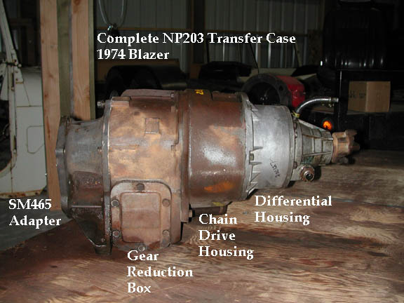
NP203:
 The
New Process 203 is the largest transfer case I have seen in domestic trucks.
It was used in 1971-'80 GM K-series trucks, Blazers and Suburbans, 1974-'76
Ford F-150 and Broncos, and 1971-'80 Dodge Ram and Ramcharger trucks. It consists
of three basic components: 1) a cast-iron gear reduction box containing massive
helical input, idler and output gears with a low-range ratio of 2.0:1; 2) a
cast-iron case housing containing a 3"-wide chain drive for the front output
assembly, and 3) a differential gearset allowing for full-time operation of
the transfer case, The differential, along with the output yoke and speedometer
gear is housed in an aluminum tail houising. The overall size, chain drive and
the differential have not made this a popular transfer case for serious off-road
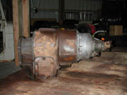
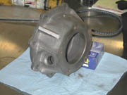
enthusiasts. What has made it popular is the fact that the gear reduction
box (GRB) can be separated from the rest of the unit and used as the front half
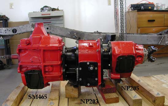
of a double transfer case assembly. The image to the left shows a complete NP203
that was originally mated to an SM465. The image shows the SM465 adapter, the
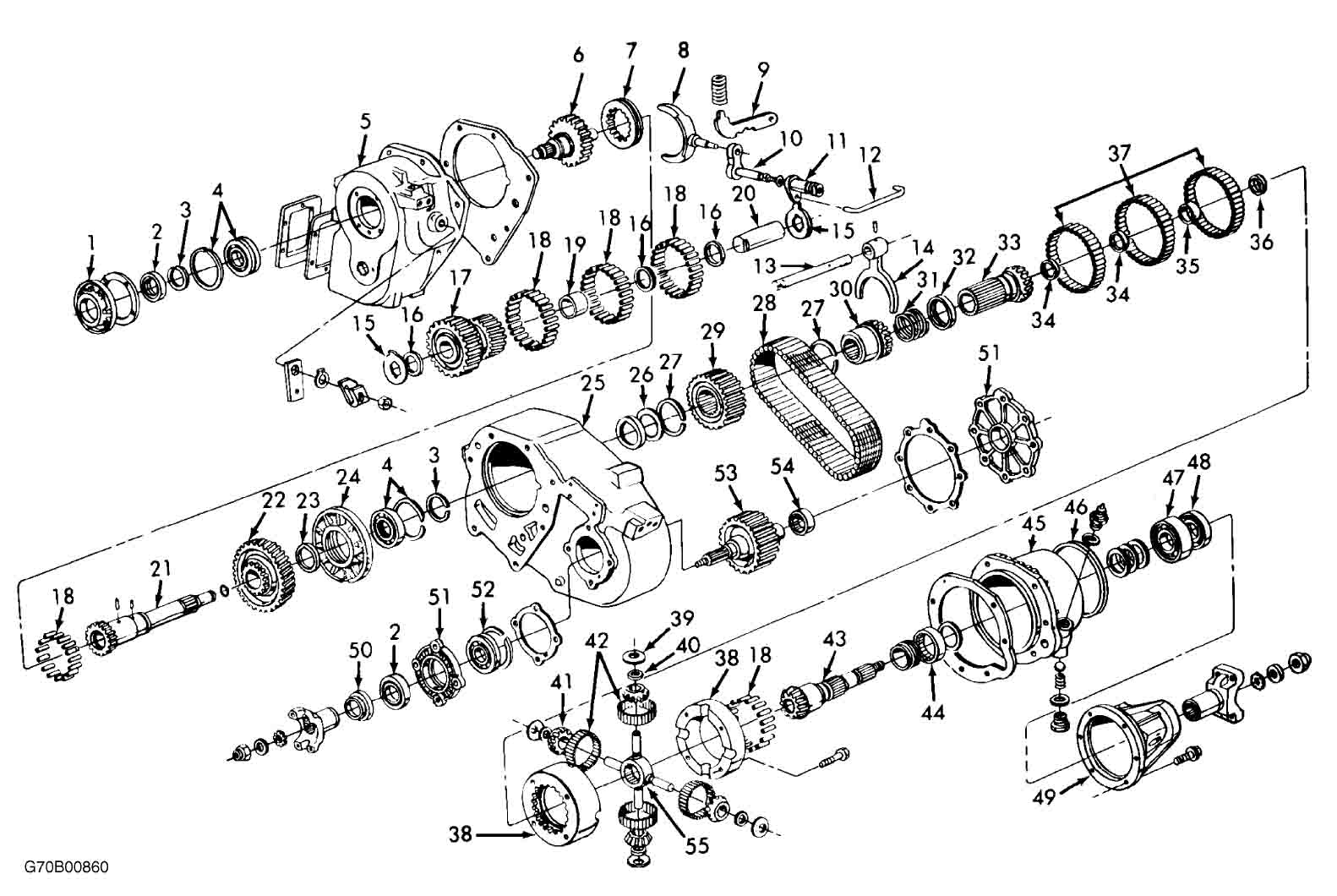
GRB, chain unit and differential tail housing. Here is an exploded
view diagram of the NP203.
The
New Process 203 is the largest transfer case I have seen in domestic trucks.
It was used in 1971-'80 GM K-series trucks, Blazers and Suburbans, 1974-'76
Ford F-150 and Broncos, and 1971-'80 Dodge Ram and Ramcharger trucks. It consists
of three basic components: 1) a cast-iron gear reduction box containing massive
helical input, idler and output gears with a low-range ratio of 2.0:1; 2) a
cast-iron case housing containing a 3"-wide chain drive for the front output
assembly, and 3) a differential gearset allowing for full-time operation of
the transfer case, The differential, along with the output yoke and speedometer
gear is housed in an aluminum tail houising. The overall size, chain drive and
the differential have not made this a popular transfer case for serious off-road
enthusiasts. What has made it popular is the fact that the gear reduction
box (GRB) can be separated from the rest of the unit and used as the front half
of a double transfer case assembly. The image to the left shows a complete NP203
that was originally mated to an SM465. The image shows the SM465 adapter, the
GRB, chain unit and differential tail housing. Here is an exploded
view diagram of the NP203.
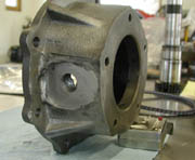
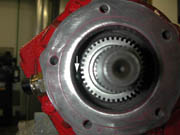
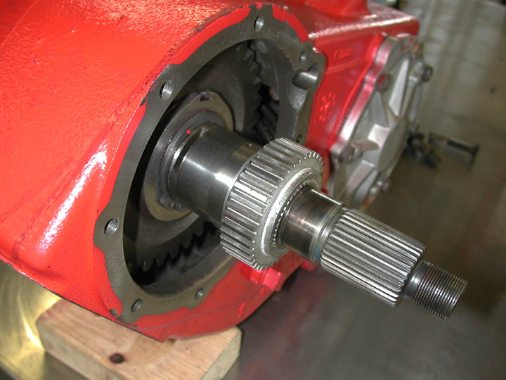
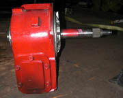 The
image to the right shows the GRB with the original output shaft which connects
to both the chain drive and the differential. As a doubler, this output shaft
must be shortened and new splines cut to mate with the transfer case mounted
to the rear of the GRB. Aftermarket shafts and adapters are available to mate
the NP203 GRB to transfer cases such as the Land Cruiser transfer case (Advance
Adapters) and the NP205 (Off-Road Design
).
The
image to the right shows the GRB with the original output shaft which connects
to both the chain drive and the differential. As a doubler, this output shaft
must be shortened and new splines cut to mate with the transfer case mounted
to the rear of the GRB. Aftermarket shafts and adapters are available to mate
the NP203 GRB to transfer cases such as the Land Cruiser transfer case (Advance
Adapters) and the NP205 (Off-Road Design
).
NP203 transfer cases are common and relatively inexpensive in
salvage yards ($50-$150). The frustrating aspect of NP203 gear boxes is that
they utilize a female input shaft that connects directly (no spud shaft or coupler)
to the transmission to which they were originally mated. This means that each
original transmission-NP203 combination used a different input gear, varying
in both length of the input shaft and the spline count (e.g., 10-spline for
the SM465, 27-spline for the TH350, and all other combinations used on Dodge
and Ford transmissions). Even more frustrating is the fact that perhaps the
most popular combination for today's conversions, namely the SM465-NP203, was
the most rarely used OEM combination. The 465-203 combination was only used
in 1974 and rare '75 Chevy Blazers. Consequently these 203 cases and their adapters
are very difficult to find.The NP203 that I ended up using was from a 1978 Dodge.
I purchased separately the adapter and a new 10-spline input gear. In many cases,
purchase of a new adapter and input gear may be the most effective means to
obtain these parts.
NP205:
The New Process 205 was used in 1971-'80 GM K-series trucks,
Blazers and Suburbans,Dodge Ram and Ramchargers and 1976-'79 Ford F-150 and
Broncos. In contrast to the 203, the NP 205 is a part-time, all-gear transfer
case. It features an all cast-iron case, massive helical gears and large input/output
shafts. It is arguably the strongest transfer case ever built for 1 ton and
smaler 4WD vehicles. The downside of the NP205 is its low-gear ratio (only 1.98:1)
and small sized case, thus preventing development of aftermarket gear sets that
might improve the low-gear ratio. Although compact, it is a heavy transfer case,
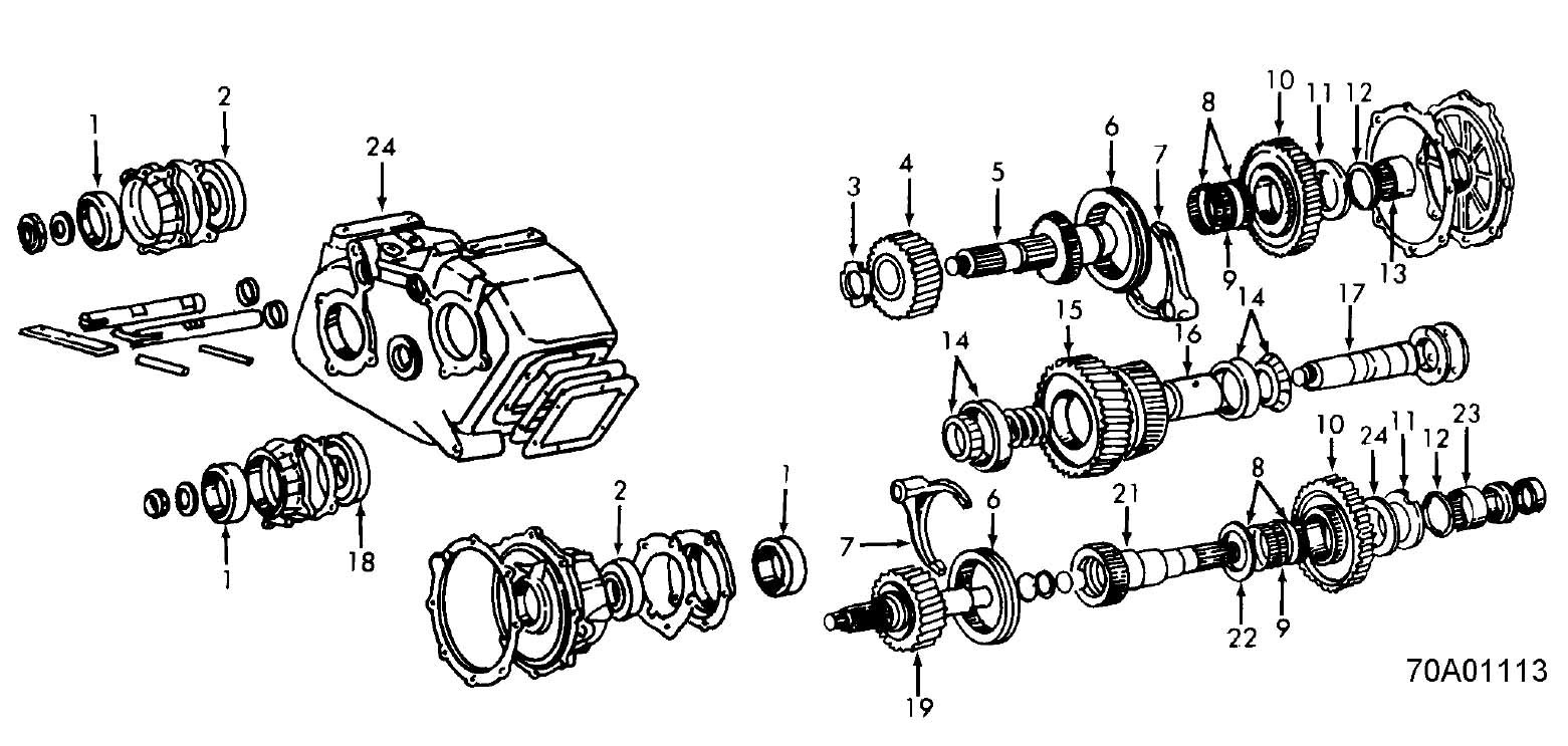
and I have yet to hear of one breaking. Here is an exploded
view diagram of an NP205.
Like the NP203, the NP205 came with several input gear configurations
and evolved over time. GM used 4 different input gears in the 205:
- 10-spline male input which came mated to the SM465 manual
transmission. GM used a fully splined female drive sleeve to mate the male
SM465 transmission output shaft to the male NP205 input gear. The large splines
on the input gear routinely wear, and are not well suited to receive the high
torque of an additional gear reduction box in front of the transfer case.
- 27-spline male input which came mated to the TH350 transmission.
It also used a female drive sleeve between the transmission output shaft and
the male NP205 input.
- The biggest and best version of the
NP205 for a double transfer case arrangement has a 32-spline, female input
gear . This version came from the factory mated to the TH400 transmissions.
It wears very well and does not use a drive sleeve, so there is one less splined
connection to create backlash in the drivetrain. This female input shaft sticks
out of the 205 case by about 1 1/4" and the male transmission shaft plugs
directly into it. This allows for a short adapter mating the two t-cases.
- The last few years of GM's use of the NP205 included a case
that used a round bolt pattern and "long" 32 spline female input
gear. This was used behind the later model SM465 and later TH400 transmissions
from about '85 to '91 in straight axle, 1-ton trucks.The round bolt pattern
is similar to that used on the Ford models. The input gear sticks out of the
205 case by about 3 1/2", and this length must be added to any adapter
in front of the 205 t-case.
I had access to a very reasonably priced 1991 NP205 with the
long 32-spline input gear, and chose to simply replace the input for the shorter
TH400 style input gear. I also selected the Off Road Design adapter. Steven
Watson at ORD was very helpful in customizing the adapter for my late-model
205 housing and in clocking the 205 so that its bottom is level with the bottom
of the NP203 and the SM465. I am pleased with the quality of the fabrication,
and the ORD adpter and output shaft make for an easy conversion.
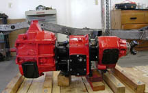
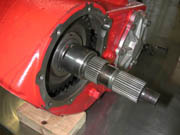
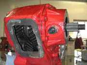
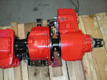 The
complete assembly of gear boxes is shown in these images. The total length of
the gearboxes is 37.75 inches and includes the SM465 (12"), 465-203 adapter
(4.5"), NP203 GRB (5.75), 203-205 adapter (3") and NP 205 (12.5"
from front surface to the center of the rear output yoke). Although too long
for a short-wheel-base FJ40, the 105" WB of the truggy is ideal. The combination
of big iron cases makes it heavy compared to an Atlas II, but I doubt anyone
would question the strength of these gear boxes. After breaking several Land
Cruiser transfer cases over the years, I look forward to having a builletproof
drivetrain.
The
complete assembly of gear boxes is shown in these images. The total length of
the gearboxes is 37.75 inches and includes the SM465 (12"), 465-203 adapter
(4.5"), NP203 GRB (5.75), 203-205 adapter (3") and NP 205 (12.5"
from front surface to the center of the rear output yoke). Although too long
for a short-wheel-base FJ40, the 105" WB of the truggy is ideal. The combination
of big iron cases makes it heavy compared to an Atlas II, but I doubt anyone
would question the strength of these gear boxes. After breaking several Land
Cruiser transfer cases over the years, I look forward to having a builletproof
drivetrain.
NP205 Upgrades
In addition to replacing the NP205 input gear with a new unit,
two additional upgrades were made to the primary transfer case.
1. Twin Stick Shifting:
In the stock configuration, the NP205 is shifted by a single
stick shifter capable of accessing N, 2WD high range, 4WD high range and 4WD
low range. The 205 has two shift-fork/rail systems -- one controls the range
and the other engages the front wheel output shaft. The two shift rails are
connected to each other by two mechanisms: First, at the shift lever relay rod
(this allows the box to be shifted with a single shift lever); Secondly, independent
movement of the two rails is restricted by two spring-loaded interlock pins,
oriented perpendicular to the shift rails and constrained to detents ground
into the shift rails.Shiftrails (#36) and interlock pins (#37) are shown in
the NP205 Schematic diagram. The shift lever
connection (#35), located at the end of the shift rails can easily be removed
and the single shift lever replaced by a twin stick assembly, thus allowing
control of the two shift rails. However, this modification alone does not allow
for any sort of independent movement of the two shift rails. The interlock
pins still prevent independent movement. The interlock pins are important because
they limit the movement of the shift rails and hence the gear combinations that
can be selected. It is possible to remove the interlock pins entirely, but that
would allow for completely independent shifting along the two shift rails. This
would allow, for example, the transfer case to simultaneously be placed in rear
wheel low range and front wheel high range -- obviously not a good thing. Fortunately
a compromise exists that allows for independent control of the front and rear
output, but not mixing of high and low range. This modification allows one output
to be shifted into neutral while the other is in either low or high range. Specifically
useful is the possibility of shifting the rear output into neutral and keeping
the front wheels in low range. With the modifications described below, one shift
lever controls the rear output while the other controls the front. Shift options
for each include H - N - L, but a mix of H and L between front and rear is still
prevented by the interlock pins. The Atlas also provides this capability and
a Dana 300 can be modified to do it as well.
This is a very easy modification. It simply involves increasing
the size of the two detents in the range shift rail. In order to do this, the
shift rail must be removed from the transfer case. The procedure is easiest
if the inspection cover is removed, thus allowing access to the shift fork.
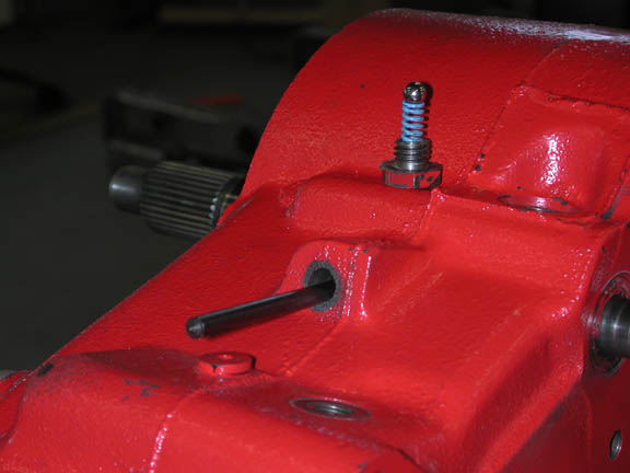
 First
you need to remove the detent ball and spring (blue) that connects the range
shift rail with the front interlock pin. I also recommend removing or at least
loosening the spring on the other end of the interlock pin (the one connexting
the front wheel drive shift rail). Simply remove the cap and spring. The ball
can be retrieved with a small magnet.
First
you need to remove the detent ball and spring (blue) that connects the range
shift rail with the front interlock pin. I also recommend removing or at least
loosening the spring on the other end of the interlock pin (the one connexting
the front wheel drive shift rail). Simply remove the cap and spring. The ball
can be retrieved with a small magnet.
 Remove
the small rubber freeze plug located between the two shift rails and oriented
perpendicular to the range shift rail. Removing this plug allows access to the
shift fork. The shift rail is connected to the Hi-Lo range shift fork with a
roll pin pressed through the fork and rail. With an appropriate punch or allen
wrench drive the roll pin out through the fork and rail. It will fall down into
the case, but it can be retrieved through the inspection cover. You should now
be able to pull the range rail out of the case. If the shift rail will not come
out, you might have to shift the front wheel drive shift rail into neutral.
In order to prevent the shift fork from moving once the rail is removed, place
an allen wrench or punch through the tunnel in the case and the hole in the
shift fork.
Remove
the small rubber freeze plug located between the two shift rails and oriented
perpendicular to the range shift rail. Removing this plug allows access to the
shift fork. The shift rail is connected to the Hi-Lo range shift fork with a
roll pin pressed through the fork and rail. With an appropriate punch or allen
wrench drive the roll pin out through the fork and rail. It will fall down into
the case, but it can be retrieved through the inspection cover. You should now
be able to pull the range rail out of the case. If the shift rail will not come
out, you might have to shift the front wheel drive shift rail into neutral.
In order to prevent the shift fork from moving once the rail is removed, place
an allen wrench or punch through the tunnel in the case and the hole in the
shift fork.
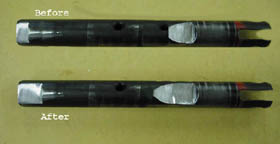 The
key to this modification is to increase the size of the indents in the range
shift rail only. The image to the left shows how I modified the rail. Each detent
was enlarged by 7/16" (0.4375"). The exact value does not appear critical
and I do not know how much slop in this value is acceptable. Note that the detent
at the rear of the shaft remains abrupt and the detent on the front remains
a slope. Enlarging these detents allows the range shift fork, controlling the
rear output shaft, to be shifted to the neutral position while the front-wheel-drive
shift rail remains in either Hi or Low, and allows the front-wheel-drive rail
to be shifted into neutral while the rear remains in either Hi or Low.
The
key to this modification is to increase the size of the indents in the range
shift rail only. The image to the left shows how I modified the rail. Each detent
was enlarged by 7/16" (0.4375"). The exact value does not appear critical
and I do not know how much slop in this value is acceptable. Note that the detent
at the rear of the shaft remains abrupt and the detent on the front remains
a slope. Enlarging these detents allows the range shift fork, controlling the
rear output shaft, to be shifted to the neutral position while the front-wheel-drive
shift rail remains in either Hi or Low, and allows the front-wheel-drive rail
to be shifted into neutral while the rear remains in either Hi or Low.
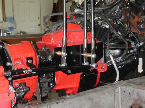
 The
three shifters I built for the transfer cases are shown in the picture to the
right. The stick to the rear shifts the NP203 (H-N-L)
and the two sise-by-side sticks are for the NP205. The 205 stick on the left
controls the rear wheel drive (H-N-L) while the stick on the right controls
the front wheel drive (H-N-L).
The
three shifters I built for the transfer cases are shown in the picture to the
right. The stick to the rear shifts the NP203 (H-N-L)
and the two sise-by-side sticks are for the NP205. The 205 stick on the left
controls the rear wheel drive (H-N-L) while the stick on the right controls
the front wheel drive (H-N-L).
Electronic Vehicle Speed Sensor:
The gear boxes in the truggy are mated to a Vortec
engine identical to the one in my FJ40. A critical component of the Vortec
sensor/computer system is the Vehicle Speed Sensor (VSS). The Vortec computer
uses the signal from the VSS to monitor and control a number of important engine
parameters, including the fuel:air mixture. I wanted to add capabilities of
adding a GM VSS to the NP205. This conversion includes replacing the standard
speedometer worm gear with a steel reluctor ring and adding a GM electronic
vehicle speed sensor (VSS). The VSS consists of a magnetic tip and coil that
produces an electronic pulse each time one of the "teeth" of the reluctor
ring passes by the tip. The number of pulses produced per minute is proportional
to the rpm of the output shaft of the transfer case.
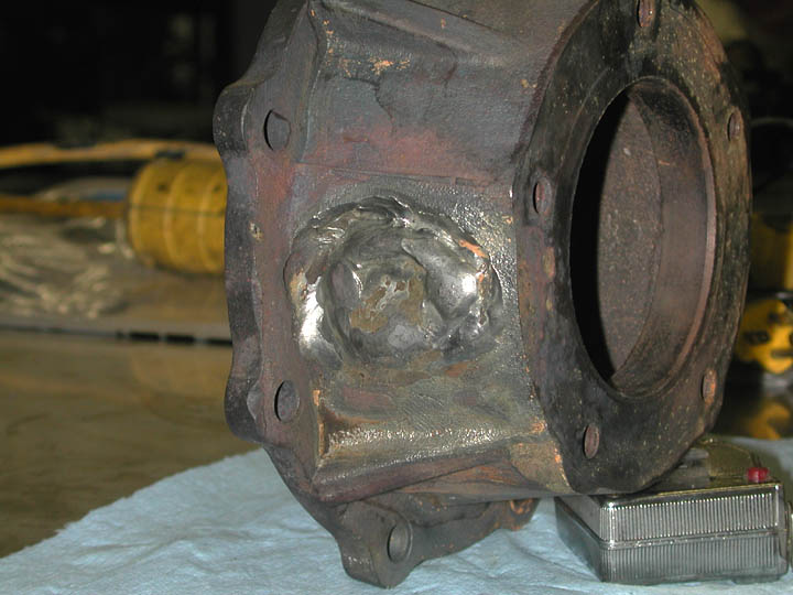
 The
most challenging part of this little project was making a new boss in the NP205
tail housing to hold the GM speed sensor. A traditional speedometer gear on
the output shaft of the T-case drives the speedometer cable by a gear that sits
below the output shaft. In contrast, the VSS must be oriented exactly perpendicular
to the output shaft and reluctor ring. This required filling in the old speedometer
boss and machining a new one for the VSS. I was worried about welding so much
on the cast iron tail housing and the potential for warping the housing. I called
on my friend Senkovitch who has expereince welding cast iron. The procedure
we used included slow heating to bring the entire housing to a temperature of
near 700 degrees. We then welded in the old boss
using a TIG welder and a large cast iron welding rod. Following completion of
the welding, we insulated the housing and allowed it to cool overnight. The
next day we put the housng on the lathe and checked for any warpage. The runout
on the bearing journal was less than 0.002" so we were satisfied we had
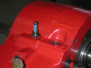
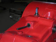
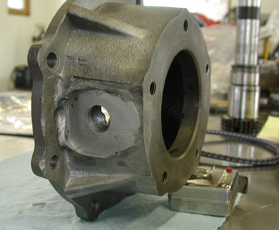
not induced any deformation or warpage.The image on the left shows the housing
with the original boss -- note how the speedometer fitting angles down toward
the bottom of the output shaft. The image on the right shows
the new boss machined into the tail housing. I build a jig to hold the housing
on the table of the milling machine and machined the weleded area flat. I then
drilled and tapped the hole to fit the GM sensor.
The
most challenging part of this little project was making a new boss in the NP205
tail housing to hold the GM speed sensor. A traditional speedometer gear on
the output shaft of the T-case drives the speedometer cable by a gear that sits
below the output shaft. In contrast, the VSS must be oriented exactly perpendicular
to the output shaft and reluctor ring. This required filling in the old speedometer
boss and machining a new one for the VSS. I was worried about welding so much
on the cast iron tail housing and the potential for warping the housing. I called
on my friend Senkovitch who has expereince welding cast iron. The procedure
we used included slow heating to bring the entire housing to a temperature of
near 700 degrees. We then welded in the old boss
using a TIG welder and a large cast iron welding rod. Following completion of
the welding, we insulated the housing and allowed it to cool overnight. The
next day we put the housng on the lathe and checked for any warpage. The runout
on the bearing journal was less than 0.002" so we were satisfied we had
not induced any deformation or warpage.The image on the left shows the housing
with the original boss -- note how the speedometer fitting angles down toward
the bottom of the output shaft. The image on the right shows
the new boss machined into the tail housing. I build a jig to hold the housing
on the table of the milling machine and machined the weleded area flat. I then
drilled and tapped the hole to fit the GM sensor.
 The
image to the left shows the output shaft of the NP205. The inner set of splines
held the original teflon speedometer gear. Some of the later model NP205s used
a reluctor ring instead of the traditional speedometer worm gear. I purchased
a 40-tooth reluctor ring for a 1991 NP205 and that fit perfectly on the output
shaft. It turns out that GM did use an NP205 with an electronic VSS in 1991
model year one-ton Crew Cab trucks. To my knowledge, that was the ONLY application
of an NP205 with a VSS. The transfer case and tail housing are essentially impossible
to find. Reluctor rings are avaialble as the same size and spline count were
used in the later Borg-Warner transfer cases. The image on the right shows the
output shaft with the reluctor ring installed.
The
image to the left shows the output shaft of the NP205. The inner set of splines
held the original teflon speedometer gear. Some of the later model NP205s used
a reluctor ring instead of the traditional speedometer worm gear. I purchased
a 40-tooth reluctor ring for a 1991 NP205 and that fit perfectly on the output
shaft. It turns out that GM did use an NP205 with an electronic VSS in 1991
model year one-ton Crew Cab trucks. To my knowledge, that was the ONLY application
of an NP205 with a VSS. The transfer case and tail housing are essentially impossible
to find. Reluctor rings are avaialble as the same size and spline count were
used in the later Borg-Warner transfer cases. The image on the right shows the
output shaft with the reluctor ring installed.
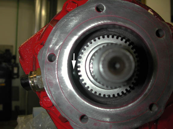
 The
image to the left showns the completed tail housing with the VSS installed in
the newly machined boss. The image to the right shows the tip of the VSS (arrow)
located approximately 0.040" from the surface of the reluctor ring.
The
image to the left showns the completed tail housing with the VSS installed in
the newly machined boss. The image to the right shows the tip of the VSS (arrow)
located approximately 0.040" from the surface of the reluctor ring.
The only other modification I am considering for the NP205 is
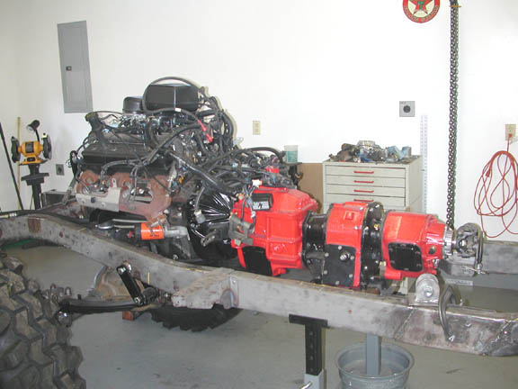
to add a disc parking brake and new driveshaft yoke on the rear output shaft.
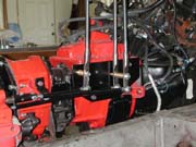
Here is a view of the complete drivetrain, showing the Vortec
engine and the gearboxes.
 The
New Process 203 is the largest transfer case I have seen in domestic trucks.
It was used in 1971-'80 GM K-series trucks, Blazers and Suburbans, 1974-'76
Ford F-150 and Broncos, and 1971-'80 Dodge Ram and Ramcharger trucks. It consists
of three basic components: 1) a cast-iron gear reduction box containing massive
helical input, idler and output gears with a low-range ratio of 2.0:1; 2) a
cast-iron case housing containing a 3"-wide chain drive for the front output
assembly, and 3) a differential gearset allowing for full-time operation of
the transfer case, The differential, along with the output yoke and speedometer
gear is housed in an aluminum tail houising. The overall size, chain drive and
the differential have not made this a popular transfer case for serious off-road
enthusiasts. What has made it popular is the fact that the gear reduction
box (GRB) can be separated from the rest of the unit and used as the front half
of a double transfer case assembly. The image to the left shows a complete NP203
that was originally mated to an SM465. The image shows the SM465 adapter, the
GRB, chain unit and differential tail housing. Here is an exploded
view diagram of the NP203.
The
New Process 203 is the largest transfer case I have seen in domestic trucks.
It was used in 1971-'80 GM K-series trucks, Blazers and Suburbans, 1974-'76
Ford F-150 and Broncos, and 1971-'80 Dodge Ram and Ramcharger trucks. It consists
of three basic components: 1) a cast-iron gear reduction box containing massive
helical input, idler and output gears with a low-range ratio of 2.0:1; 2) a
cast-iron case housing containing a 3"-wide chain drive for the front output
assembly, and 3) a differential gearset allowing for full-time operation of
the transfer case, The differential, along with the output yoke and speedometer
gear is housed in an aluminum tail houising. The overall size, chain drive and
the differential have not made this a popular transfer case for serious off-road
enthusiasts. What has made it popular is the fact that the gear reduction
box (GRB) can be separated from the rest of the unit and used as the front half
of a double transfer case assembly. The image to the left shows a complete NP203
that was originally mated to an SM465. The image shows the SM465 adapter, the
GRB, chain unit and differential tail housing. Here is an exploded
view diagram of the NP203.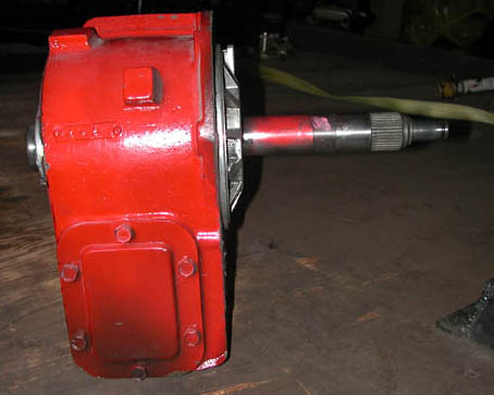


