
We initialy elected to take advantage of the internally lubricated Vortec A/C compressor to power an on-board compressed air system. The photo below shows the original assembly with the compressor with input and output lines modified to include a K&N filter on the input side and a high-pressure rubber hose (blue) connecting the compressor to a custom fabricated air block.
Unfortunately, like all vane-style compressors, the lubrication for the compressor must come from the refrigerant. When used as an air compressor, the unit is not sufficiently lubricated. We installed an in-line oiler (similar to those used to lubricate air tools) in the hope that would provide sufficient lubrication. It did not! The compressor lasted three years of very mild use before giving up the ghost.
The solution was to replace the vane-style compressor with a reciprocating-style (i.e,. piston and valve) compressor with an internal lubrication reservoir. We elected to switch to the classic upright York compressor. Specifically, we chose a 10 c.i.d. York compressor, capable of producing 4 CFM at 90 psi, operating at 1200 rpm. I found a low-cost ($40) unit from a 1983 Mustang in a salvage yard. This choice was based on the fact that it appears to be the only make and year of the upright York that came factory equipped with a serpentine clutch assembly. Although the clutch appeared to be in excellent condition, its electromagnet was positioned behind the actual pulley making the entire assembly very long -- in fact too long to mount on the Vortec. I ended up purchasing a new serpentine clutch assembly from Kilby Enterprises.
 Mounting
of the York proved to be a bit of a challenge. As you can see from the
first photo in this chapter, there is not a lot room in the engine bay.
More importantly, with a serpentine-belt system, each belt-driven accessory
must be integrated with all others. Furthermore, the mounting bracket for
the stock A/C compressor is a large cast aluminum unit that also holds
the power steering pump. I basically had to modify the Vortec A/C
and PS bracket to accomodate the York compressor. This was done by cutting
and milling off the top of the stock bracket and then welding two upright
mounting plates to the stock bracket as shown in the photo to the right.
Alignment of the pulley requires that the rear of the compressor overlaps
with the front of the valve cover.
Mounting
of the York proved to be a bit of a challenge. As you can see from the
first photo in this chapter, there is not a lot room in the engine bay.
More importantly, with a serpentine-belt system, each belt-driven accessory
must be integrated with all others. Furthermore, the mounting bracket for
the stock A/C compressor is a large cast aluminum unit that also holds
the power steering pump. I basically had to modify the Vortec A/C
and PS bracket to accomodate the York compressor. This was done by cutting
and milling off the top of the stock bracket and then welding two upright
mounting plates to the stock bracket as shown in the photo to the right.
Alignment of the pulley requires that the rear of the compressor overlaps
with the front of the valve cover.
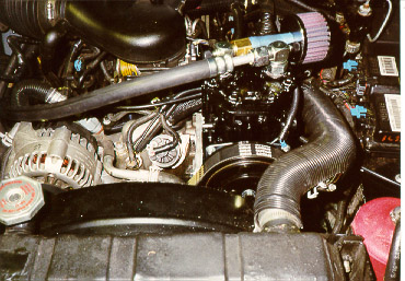 The
final assembly is shown in the photo to the left. Because the upright York
is a tall compressor (compared to the vane-style) and the mounting flanges
are on the top, clearance with the Cruiser's hood must also be considered.
The compressor cannot be raised too high over the valve cover without having
the input/output fittings hit the hood. Correct positioning and design
of the mounting bracket is thus critical. Indeed, the fit is very tight
in all dimensions. In fact, the small air cleaner almost prevents
closure of the hood. Even though I tried to accurately reposition
the center of the compressor drive shaft, the OEM serpentine belt was more
than an inch too short for the York. The new clutch is larger and I was
not able to set the unit as low as I wanted without hitting the valve cover.
BUT, IT FITS and works great!!
The
final assembly is shown in the photo to the left. Because the upright York
is a tall compressor (compared to the vane-style) and the mounting flanges
are on the top, clearance with the Cruiser's hood must also be considered.
The compressor cannot be raised too high over the valve cover without having
the input/output fittings hit the hood. Correct positioning and design
of the mounting bracket is thus critical. Indeed, the fit is very tight
in all dimensions. In fact, the small air cleaner almost prevents
closure of the hood. Even though I tried to accurately reposition
the center of the compressor drive shaft, the OEM serpentine belt was more
than an inch too short for the York. The new clutch is larger and I was
not able to set the unit as low as I wanted without hitting the valve cover.
BUT, IT FITS and works great!!
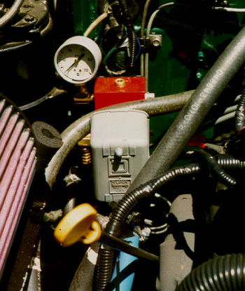 The
air block (red) is mounted on a bracket extending forward from the passenger's-side
firewall rib. It contains six NPT-threaded ports, including input,
output, pressure gauge, and three auxillary ports (two of which are planned
for future ARB locker connections). The input port is connected to
a pressure cut-off switch (grey). The Vortec compressor contains its own
high- and low-pressure switches which control (through the VCM and dash-mounted
air-request switch) operation of the A/C compressor clutch mechanism.
Unfortunately the stock A/C system was designed to operate at pressures
in excess (e.g., 200 psi) of those desired for a normal air compressor,
so a lower, high-pressure (adjustable) switch is required. The Vortec
high-pressure switch was therefore bypassed with a new circuit incorporating
the adjustable pressure switch on the air block.
The
air block (red) is mounted on a bracket extending forward from the passenger's-side
firewall rib. It contains six NPT-threaded ports, including input,
output, pressure gauge, and three auxillary ports (two of which are planned
for future ARB locker connections). The input port is connected to
a pressure cut-off switch (grey). The Vortec compressor contains its own
high- and low-pressure switches which control (through the VCM and dash-mounted
air-request switch) operation of the A/C compressor clutch mechanism.
Unfortunately the stock A/C system was designed to operate at pressures
in excess (e.g., 200 psi) of those desired for a normal air compressor,
so a lower, high-pressure (adjustable) switch is required. The Vortec
high-pressure switch was therefore bypassed with a new circuit incorporating
the adjustable pressure switch on the air block.
 From
the air block, we installed a high-pressure rubber hose running along the
passenger's-side frame to a 3 gallon air tank tucked under the body just
fore of the rear frame crossmember/bumper. This tank is the type used on
semi truck/tractors for their air brake reservoir, and was obtained from
a salvage yard. It is shown in the photo below. The tank includes
a fitting for quick connection to an air hose to inflate tires or to operate
air tools.
From
the air block, we installed a high-pressure rubber hose running along the
passenger's-side frame to a 3 gallon air tank tucked under the body just
fore of the rear frame crossmember/bumper. This tank is the type used on
semi truck/tractors for their air brake reservoir, and was obtained from
a salvage yard. It is shown in the photo below. The tank includes
a fitting for quick connection to an air hose to inflate tires or to operate
air tools.