Dana 60 Axles
For an especially informative and well-written
website on dana 60 front axles see Billavista's
site
Part One: Narrowing a front Dana 60 axle for a Land Cruiser
Land Cruiser axles are relatively strong and rarely break in stock rigs
or even modified trail rigs running tires up to 36" tall with locked differentials.
The axle shafts themselves are approximately 1.3" in diameter and connect
with the side gears with 30 splines. These axles are roughly equivalent with
those found in Dana 44 units. The bane of the offroad Cruiserhead running big
tires and locked differentails on tough trails is, of course, the Birfield joints.
In building a trail rig, it is therefore common to either replace the Birfields
with stronger cv joints such as Longfields or replace the axles and u-jointsDana
44 units, or replace the entire axle assemblies.Common replacement front axles
include Dana 44 and Dana 60 assemblies or more rarely the enormous Rockwell
2.5 ton axles. The Dana 60 (D60) front axles found in GM, Ford and Dodge 1 ton
4WD trucks are arguably the strongest and most appropriate choice for upgrading
both front and rear axles for hard-core wheeling. The front Dana 60 inner axle
shafts are 1.5" in diameter and have 35 splines. The u-joints are considerably
stronger than those in the D44 and the outer stub shafts can be upgraded to
1.5", 35-spline shafts. In short, the D60 was the ideal upgrade axle for
the 45 truggy.
Custom Dana 60 axle housings are available from several aftermarket dealers
such as Currie, Dynatrack and Sunray. These are quality axle replacements, but
unfortunately they carry a considerable price tag. What follows is a do-it-yourself
guide to D60 modifications.
In considering a D60 axle swap, careful attention and planning must be given
to the desired width of the axle and the spring configuration. OEM Dana 1-ton
front axle widths are 69" between wheel mounting surfaces (WMS). For comparison,
the stock Land Cruiser width is 55". With typical 10" wheels and tires14+"
wide, the full size track width exceeds 83". Although this width provides
great stability, it is too wide for many trails that we encounter in the NW,
and hence it is common to narrow the OEM axle assembly. If leaf springs are
used, the possible width options are limited by the fact that the D60 incorporates
one of the spring perches in the casting of the pumpkin (driver' side for Ford
D60s and passenger's side for GM and Dodge). Consequently, that mounting point
cannot be changed relative to the centerline of the axle housing. This means
that the spring configuration, specifically the distance between the spring
perches plays a large role in the possible axle widths and the modifications
required to achieve the desired width. The following possibilities exist:
-
Retain the OEM D60 WMS width. The only way to retain the
69" full-size and centered axle width with leaf springs on a Land Cruiser
frame is to relocate (outboard) both of the springs. The centers of the
Land Cruiser springs (spring perchs) are separated by 27". The centers
of GM springs are separated by 31.5" (i.e., 4.5" wider than LC
spring configuration). Thus, in order to retain the full width, the spring
and shackle hangers on the Cruiser frame must each be moved 2.25" outward
from their OEM location.
-
Retain OEM Land Cruiser Spring Perch Width and Maximum Width of the
D60. The only way to do this and keep the D60 axle centered on
the Land Cruiser frame is to narrow the D60 by removing 4.5 inches from
the driver's or "long side" of the axle housing and axle shaft.
The 4.5 " of narrowing corresponds to the difference in the widths
of the spring perches. The advantage of this option is that only one axle
tube and axle shaft need to be shortened. The option results in a WMS width
of 64.5".
-
Narrow the axle to less than 64.5" WMS. Achieving a width
of less than 64.5" requires that both of the axle tubes be shortened
and both inner axle shafts be either shortened or replaced. The formula
for shortening a normal 69" axle is to shorten the long side by 4.5"
plus one half the amount to be narrowed beyond 4.5". The short side
is narrowed by one half the amount to be narrowed beyond 4.5". For
example, in order to achieve an WMS width of 62" with the stock Land
Cruiser springs, the long side needs to be shortened by 5.75" and the
short side shortened by 1.25". While this extra narrowing is straightforward,
it is an option requiring both additional work and expense.
For the 45 Truggy project, I chose option 2. The final WMS width of 64.5
is only .5" narrower than the OEM width of my D60 rear axle. With 42x14.5x15
tires mounted on 10" beadlocks, the track width is 80" -wide enough
to provide extra stability, but not too wide so as to not fit on my trailer
and on most of the trails I like to run. And finally, not having to shorten
both sides of the D60 was both easier and less expensive.
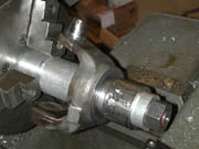
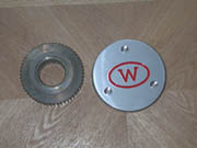
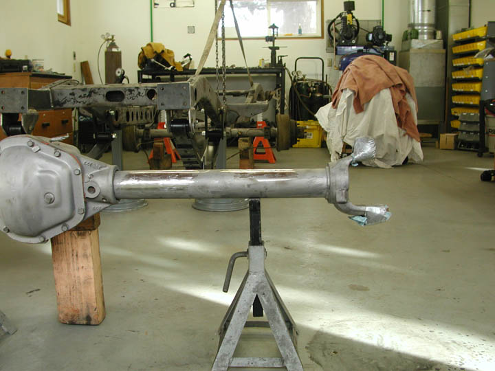
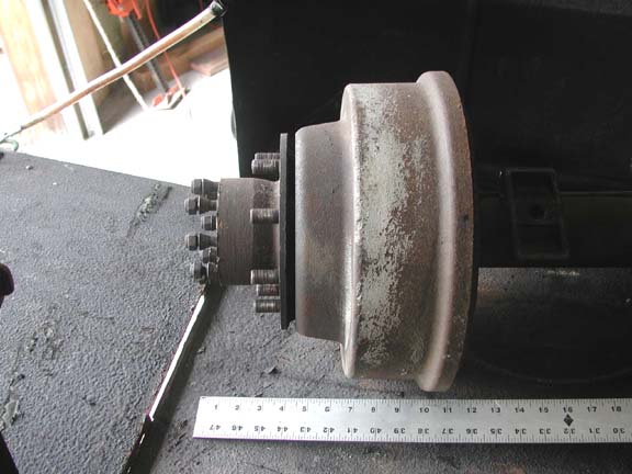
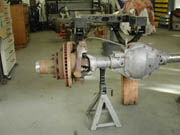 The
image to the left shows the passenger's side of the D60. This axle came out
of a 1987 Chevy 1-ton (K-30) truck. It came withn 3.54 gears, 1.5" 35-spline
inner axle shafts and 1.3" 30-spline outer stub axles. Notice the passenger's
side spring perch that is machined into the center section. The axle components
outboard of the axle tube end/king pin/knuckle include the 1) outer knuckle
housing with steering arm, 2) brake backing plate and hub assembly. Removal
involves working from the outside to the knuckle. First remove the lock-out
hubs (Warn in my case), wheel bearing lock nut, lock ring and the wheel bearing
adjusting nut. This allows the hub and brake rotor be removed from the spindle.
With the hub removed, the spindle can next be removed by simply unbolting it
from the knuckle housing. Finally the outer knuckle housing can be removed from
the king pin assembly by removal of the steering arm and the bearing caps. The
two pictures below show the axle housing first with the hub and rotor removed
and next with the spindle removed.
The
image to the left shows the passenger's side of the D60. This axle came out
of a 1987 Chevy 1-ton (K-30) truck. It came withn 3.54 gears, 1.5" 35-spline
inner axle shafts and 1.3" 30-spline outer stub axles. Notice the passenger's
side spring perch that is machined into the center section. The axle components
outboard of the axle tube end/king pin/knuckle include the 1) outer knuckle
housing with steering arm, 2) brake backing plate and hub assembly. Removal
involves working from the outside to the knuckle. First remove the lock-out
hubs (Warn in my case), wheel bearing lock nut, lock ring and the wheel bearing
adjusting nut. This allows the hub and brake rotor be removed from the spindle.
With the hub removed, the spindle can next be removed by simply unbolting it
from the knuckle housing. Finally the outer knuckle housing can be removed from
the king pin assembly by removal of the steering arm and the bearing caps. The
two pictures below show the axle housing first with the hub and rotor removed
and next with the spindle removed.
 |
 |
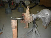
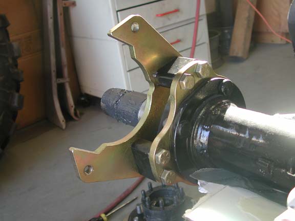
 The
driver's side of the axle with the hub, brake and knuckle housing removed is
shown on the right. I have at this stage also removed the spring perch, steering
stabilizer mount and shock mount. I have wrapped the king pin and lower bearing
assembly with duct tape to keep them clean while grinding. The king pin is screwed
into the housing at 500-600 ft. lbs., and at that time I didn't have access
to a torque wrench capable of that sort of force.I needed to visit my friend
Senkovich who has tools for working on big equipment to borrow his 5' long torque
wrench to tackle the king pins.
The
driver's side of the axle with the hub, brake and knuckle housing removed is
shown on the right. I have at this stage also removed the spring perch, steering
stabilizer mount and shock mount. I have wrapped the king pin and lower bearing
assembly with duct tape to keep them clean while grinding. The king pin is screwed
into the housing at 500-600 ft. lbs., and at that time I didn't have access
to a torque wrench capable of that sort of force.I needed to visit my friend
Senkovich who has tools for working on big equipment to borrow his 5' long torque
wrench to tackle the king pins.
There are two ways to shorten a D60 axle tube -- 1) shorten from the inside
or 2) from the outside. The inside route involves drilling or milling out the
plug welds that attach the tube to the center section and then pressing the
tube out of the center section. Once the tube is removed, it can be shortened
and then pressed back into the center section and re-welded. Since the oil seal
is located at the inner end of the axle tube, this approach also requires machining
a surface for the new oil seal.The outside route simply involves cutting off
the end of the tube with the attached king pin/ knuckle, removing the remant
tube from the inside of the king pin /knuckle and re-welding the king pin and
knuckle back onto the shortened axle tube at the correct caster angle. I opted
for the second approach figuring it would be easier. In retrospect, I am not
sure one is easier than the other.
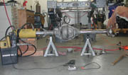
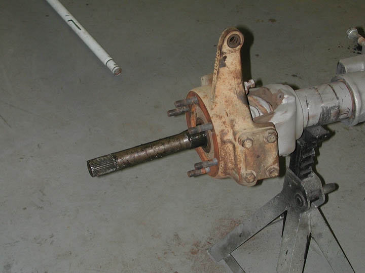
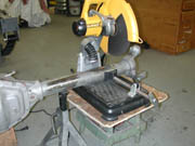 The
photo to the right shows the axle housing ready to be narrowed. After measuring,
adjusting and measuring about ten more times, the long-side axle tube is ready
to be cut off. Although the wood stool looks a bit unprofessional, with it and
some appropriate "spacers", I was able to set up the chop saw so that
the cut was square.In actual fact, since the king pin/inner knuckle assembly
is press fit onto the axle tube it is not necessary to have the cut absolutely
square.
The
photo to the right shows the axle housing ready to be narrowed. After measuring,
adjusting and measuring about ten more times, the long-side axle tube is ready
to be cut off. Although the wood stool looks a bit unprofessional, with it and
some appropriate "spacers", I was able to set up the chop saw so that
the cut was square.In actual fact, since the king pin/inner knuckle assembly
is press fit onto the axle tube it is not necessary to have the cut absolutely
square.
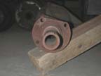
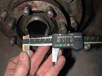
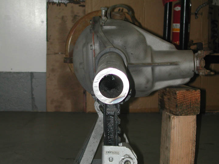
 Here is the long side of the axle housing after the end has been cut off. Can
you say beefy axle housings? No wonder the Dana 60 with 0.500" wall axle
tubes are so heavy and so strong. The outer diameter of the D60 axle tubes is
3.5 (?)"
Here is the long side of the axle housing after the end has been cut off. Can
you say beefy axle housings? No wonder the Dana 60 with 0.500" wall axle
tubes are so heavy and so strong. The outer diameter of the D60 axle tubes is
3.5 (?)"
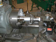
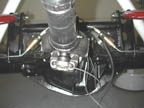
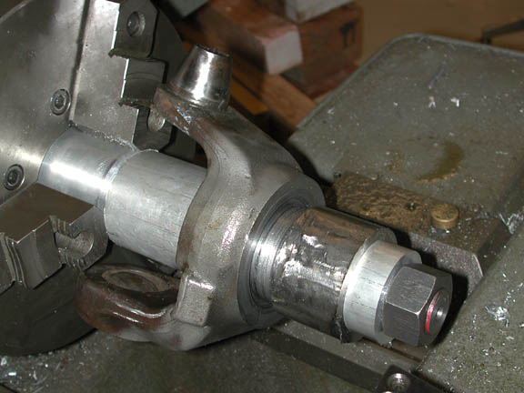
 The normal approach would be to use an angle grinder to grind off the weld between
the knuckle and the remnant of the tube. I chose to remove the weld in a big
Monarch lathe. Did I mention that I like working with machine tools? The pictures
here show the knuckle set up in the Monarch chuck and a close-up of the area
with the weld removed.
The normal approach would be to use an angle grinder to grind off the weld between
the knuckle and the remnant of the tube. I chose to remove the weld in a big
Monarch lathe. Did I mention that I like working with machine tools? The pictures
here show the knuckle set up in the Monarch chuck and a close-up of the area
with the weld removed.
With the weld completely removed on the lathe, I expected that I could simply
press the remnant of the tube out of the knuckle. Unfortunately my 20 ton shop
press and a moderate amount of heat would not break the press-fit seal between
the knuckle and remnant tube. I didn't want to heat the knuckle too hot or risk
deforming it in the press so I put it into my big vise and carefully cut through
the tube with a Sawzall. I made two cuts, 90 degrees apart with the Sawzall
blade parallel with the tube. Using a chisel, I was then able to break the tube
apart and remove the pieces from the knuckle.
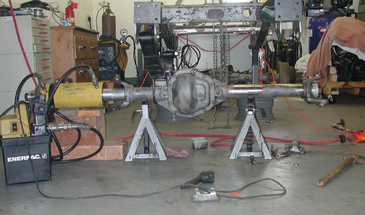
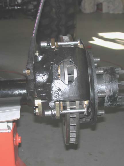
 Several
others who have done DYI narrowing of a Dana axle, have written that they were
able to use a combination of heat on the knuckle and cold on the axle tube to
force the knuckle onto the tube with a big hammer. I was not so lucky, The unmachined
o.d. of the tube was more than 0.006" greater than the i.d., of the knuckle.
Furthermore the i.d., of the knuckle had been scarred by the original press
fitting and was high in places. I carefully ground a bit off the tube with an
angle grinder and an air sander, and then "pressed" the knuckle back
onto the tube using a 200-ton, pull-type hydraulic cylinder borrowed again from
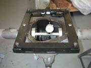
Senkovich. The image to the left shows the hydraulic cylinder set up on the
passenger's side of the axle housing pulling the knuckle onto the driver's side
tube. I used a 1.5" o.d. piece of all-thread to connect the hydraulic cylinder
to the knuckle passing through the entire length of the axle housing, and machined
two aluminum flanges to fit into the ends of the inner knuckles.
Several
others who have done DYI narrowing of a Dana axle, have written that they were
able to use a combination of heat on the knuckle and cold on the axle tube to
force the knuckle onto the tube with a big hammer. I was not so lucky, The unmachined
o.d. of the tube was more than 0.006" greater than the i.d., of the knuckle.
Furthermore the i.d., of the knuckle had been scarred by the original press
fitting and was high in places. I carefully ground a bit off the tube with an
angle grinder and an air sander, and then "pressed" the knuckle back
onto the tube using a 200-ton, pull-type hydraulic cylinder borrowed again from
Senkovich. The image to the left shows the hydraulic cylinder set up on the
passenger's side of the axle housing pulling the knuckle onto the driver's side
tube. I used a 1.5" o.d. piece of all-thread to connect the hydraulic cylinder
to the knuckle passing through the entire length of the axle housing, and machined
two aluminum flanges to fit into the ends of the inner knuckles.
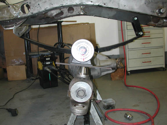
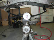 While
slowly pulling the knuckle onto the axle tube, I repeatedly checked to ensure
proper caster angle. Since I did this with no weight on the axle housing, I
could not measure true caster. Instead, I simply aimed to duplicate the same
angle of the king pin as on the passenger's side knuckle. I did this by placing
an angle finder on the top machined surface of the king pins. Although you can't
see it in this lousy picture, the angle finder measured 10 degrees rearward
tilt of the king pin. This would be considered to be a large amount of positive
caster, but the pinion will rotate upward, thus decreasing the caster when weight
is placed on the front axle. In a section below, I describe how I modified the
angle of the D60 pinion relative to the transfer case and fine-tuned the caster
angle.
While
slowly pulling the knuckle onto the axle tube, I repeatedly checked to ensure
proper caster angle. Since I did this with no weight on the axle housing, I
could not measure true caster. Instead, I simply aimed to duplicate the same
angle of the king pin as on the passenger's side knuckle. I did this by placing
an angle finder on the top machined surface of the king pins. Although you can't
see it in this lousy picture, the angle finder measured 10 degrees rearward
tilt of the king pin. This would be considered to be a large amount of positive
caster, but the pinion will rotate upward, thus decreasing the caster when weight
is placed on the front axle. In a section below, I describe how I modified the
angle of the D60 pinion relative to the transfer case and fine-tuned the caster
angle.
In re-assembly of the axle, I replaced all king pin and wheel bearings and
seals. One brake rotor had to be replaced and the other had to be resurfaced
by turning on the lathe. I rebuilt the calipers and replaced the brake pads.
The long-side axle shaft was shortened and re-splined by Dutchman
Motorsports in Portland, Orygun. Dutchman, who also made custom axle shafts
for the rear axle does exceptionally high quality work at a very reasonable
price. I highly recommend them for any axle work.
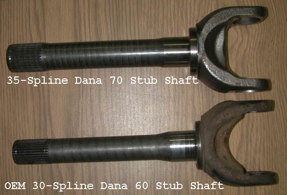
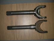 Although
the Dana 60 is clearly a strong axle assembly, it can be made even stronger
with some simple and relatively inexpensive upgrades. The inner axle shafts
are 1.5" in diameter at the end of the shaft with 35 splines; the shafts
taper upward to 1.6" along the rest of the length. In the stock configuration,
the outer stub shafts are only 1.3" in diameter and connect with the hub
along 30 splines. In the stock configuration the weakest components are the
outer stub shafts and the u-joints connecting the inner and outer axle shafts.
The picture to the left show the stock D60 outer shafts with those from a Dana
70 axle. The D70 stub shafts are a full 1.5" in diamter and have 35 splines.
The 35-spline outers can be purchased from Spicer (PN 3-82-871 for GM and Dodge)
or from custom axle shops such as Dutchman.
Although
the Dana 60 is clearly a strong axle assembly, it can be made even stronger
with some simple and relatively inexpensive upgrades. The inner axle shafts
are 1.5" in diameter at the end of the shaft with 35 splines; the shafts
taper upward to 1.6" along the rest of the length. In the stock configuration,
the outer stub shafts are only 1.3" in diameter and connect with the hub
along 30 splines. In the stock configuration the weakest components are the
outer stub shafts and the u-joints connecting the inner and outer axle shafts.
The picture to the left show the stock D60 outer shafts with those from a Dana
70 axle. The D70 stub shafts are a full 1.5" in diamter and have 35 splines.
The 35-spline outers can be purchased from Spicer (PN 3-82-871 for GM and Dodge)
or from custom axle shops such as Dutchman.
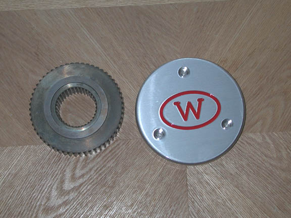
 Common
and inexpensive selectable (locking) hubs are readily available for the 30-spline
stub shafts. Aftermarket 35-spline lockable hubs are also available, but they
are expensive. Since the 45 truggy will be a dedicated trail rig, it is not
necesary to have selectable hubs. I therefore opted for a pair of 35-splineWarn
full-time lockout flanges. These flanges mate the outer axle with the hubs in
a permanently "locked" fashion. One drawback that I have heard about
the lockout flanges is that they do not utilize a spring to pullthe stubshaft
grease seals tight against the spindle, and are thus susceptable to water nincursion
if deep water crossings are common. If this is a concern or if the rig is to
be used on the highway, 35-spline Warn hubs can be obtained with part # 38786.
Common
and inexpensive selectable (locking) hubs are readily available for the 30-spline
stub shafts. Aftermarket 35-spline lockable hubs are also available, but they
are expensive. Since the 45 truggy will be a dedicated trail rig, it is not
necesary to have selectable hubs. I therefore opted for a pair of 35-splineWarn
full-time lockout flanges. These flanges mate the outer axle with the hubs in
a permanently "locked" fashion. One drawback that I have heard about
the lockout flanges is that they do not utilize a spring to pullthe stubshaft
grease seals tight against the spindle, and are thus susceptable to water nincursion
if deep water crossings are common. If this is a concern or if the rig is to
be used on the highway, 35-spline Warn hubs can be obtained with part # 38786.
There are two options for upgrading the u-joints. The least expensive option
is to replace the stock units with the new Spicer SPL55, 1480 series u-joint.
This u-joint is similar to the other 1480 joints, but is forged instead of cast.
It is said to be up to 20% stronger. CTM Racing has recently announced availability
of their new D60 super joint. This u-joint is a billet machined joint that is
super strong. Unfortunately, I have heard that the cost is near $200 per unit.
Parts List and Price Information
The following list provides information on the parts and prices of the upgrades
done on the front Dana 60 axle assembly.
|
Part
|
Part Number
|
Price
|
| Used Dana 60 Front Axle from
1 ton P.U. |
|
$800.00 |
| Shorten and Respline Inner Axle
shaft |
Dutchman Custom
|
$55.00 |
| Two Dana 70 Outer Stub Shafts |
Spicer 3-82-871 |
$140.00 |
| Warn 35-spline Lockout Flange |
WARN 39346 |
$205.89 |
| King Pin Bearings |
Spicer DA 706395X |
$56.94 |
| King Pin Seals and Gaskets |
DA-37311 and 37307 |
$15.12 |
| Two Forged 1480 Series u-joints |
Spicer SPL55-4X |
$79.12 |
| Wheel Bearings |
|
|
| Spicer 5.86 Gears and Installation
Kit |
|
$232.00 |
| ARB Locker |
ARB RD35 |
$630.00 |
|
Total
|
|
$2214.07 |
This is clearly not an inexpensive upgrade. However the cost compared to
complete aftermarket Dana 60 units still makes the DYI approach reasonable in
my opinion.
Gears
Although the dual transfer cases double the gear ratio of the
transmission relative to a single NP203 or NP205, neither of these transfer
cases are particularly low geared (~2:1). With the granny low gear of the SM465
(6.55) and double low of the transfer cases, the crawl ratio with typical 4.11
gears in the differentials is 107:1 Although this ratio would be great with
an automatic transmission, with a manual and the 42" tires, the Truggy
needed lower gears. Another advantage of the Dana 60 is the wide range of ring
and pinion gear ratios available, especially the high numerical ratios used
by the drag racing and off-road communities. For the Truggy, I elected to replace
the original 4.11 R&P gear sets with 5.86:1 gears, thereby resulting in
a final crawl ratio of 154:1.
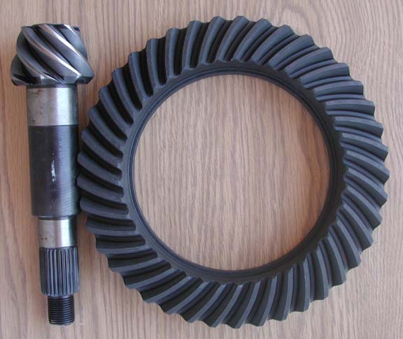
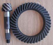 There
are several aftermarket suppliers of ring and pinion gear sets. My preference
is to spend a few dollars more and buy genuine Dana/Spicer gears, bearings and
required parts such as shims and gaskets. The 5.86 R&P gear set consists
of a ring gear with 41 teeth and a pinion gear with 7 teeth. Although the pinion
head is considerably smaller that those in 4.x combinations, I do not buy the
myth that the pinion is weaker (nor do engineers from afermarket gear makers,
I might add).
There
are several aftermarket suppliers of ring and pinion gear sets. My preference
is to spend a few dollars more and buy genuine Dana/Spicer gears, bearings and
required parts such as shims and gaskets. The 5.86 R&P gear set consists
of a ring gear with 41 teeth and a pinion gear with 7 teeth. Although the pinion
head is considerably smaller that those in 4.x combinations, I do not buy the
myth that the pinion is weaker (nor do engineers from afermarket gear makers,
I might add).
In terms of tolerances, the differential is the most precise
component in an automobile. The gears must be set up within a few thousands
of an inch in order for the differential to work properly and last. Do-it-yourself
ring and pinion installation is usually discouraged, and I have great respect
for the professionals who do this for a living. However, if you understand the
requirementas, have the necessary tools and most of all have patience, setting
up R&P gears is not out of the question for the do-it-yourself individual.
There are four critical settings that must be made in any differential. In the
order they are commonly made, these include:
- Pinion depth -- the fore-aft position of the gear
teeth on the pinion relative to the ring gear. Because the ring gear is always
centered with respect to the axle shafts and the center of the axle housing,
the pinion depth is set by moving the pinion shaft fore or aft with shims
placed between the rear pinion bearing and the housing. Each differential
type (e.g., Dana 60) has a nominal pinion depth measured from the center axis
of the ring gear to the top of the pinion head. For the D60 this is 3.125".
However each ring and pinion gear set is different, so there is no such thing
as an absolute pinion depth. Each ring and pinion gear set will have numbers
engraved on the top of the pinion head. One is a + or - number giving the
best pinion depth to be added in thousands of an inch to the nominal value
for the differential type. For example a D60 pinion head inscribed with +
3 would indicate an ideal pinion depth of 3.128".
- Pinion bearing preload -- the
preload placed on the front pinion bearing by the pinion nut holding the yoke
onto the pinion shaft. Setting of this preload is either accomplished by shims
or a chrushable sleeve placed between the rear edge of the front bearing and
the differential housing. The preload setting is typically measured by the
torgue in inch-pounds required to rotate the pinion shaft with the pinion
nut tightened to its nominal value (240-300 ft. lbs. on a D60).
- Backlash -- the "play" that exists between
the ring and pinion gears at the ideal depth setting. The ring gear is centered
on the axis of the axles, but the whole carrier can move laterally left and
right relative to the pinion gear. This lateral movement affects the depth
of tooth contact between the pinion teeth and the ring gear once the pinion
gear has been set at the proper depth. Too much backlash results in a "loose"
differential that will have excessive play and whine. Too little backlash
will result in overheating and premature wear. With Toyota differentials the
backlash is set by moving the whole carrier left to right with the adjustable
carrier bearing caps. Setting the backlash properly on a D60 is much more
difficult because it is done entirely by placing shims between the inner edge
of each carrier bearing and the carrier. Backlash is increased by adding shims
on the passengers side and removing an equivalent thickness of shims from
the driver's side.
- Carrier bearing preload -- the preload placed on the
two carrier bearings. In essence this establishes the pressure between the
carrier bearings and the axle housing.With Toyota differentials the preload
as well as backlash is set using the adjustable carrier bearing
caps. With Dana/Spicer differentials the carrier preload is also set with
shims. The basic premise is that when the backlash is properly set there is
zero space between the carrier shims. Preload is accomplished by adding additional
shim thickness (e.g., 0.015") to the already "tight" carrier
bearings.
Tools
 Regardless
of one's experience or expertise, you simply can't change ring and pinion gears
correctly without the proper tools. First and foremost is an adequate and safe
press required to install and remove the bearings onto the pinion shaft and
on the carrier. I use a 20 ton hydraulic press and would not like to do this
job with a smaller unit. For the Dana 60 differentials I also elected to build
two special service tools that could have been purchased. The first is a pinion-depth-measuring
tool that consists of a dial indicator positioned to acurately measure the distance
between the centerline of the axle housing and the top of the pinion head. The
second tool I made is one that spreads the axle housing and allows for the carrier
and carrier bearing and preload shims to be more easily inserted and removed
from the housing. The astute reader the above differential settings will note
that with a Dana differential, the carrier shims are added after the carrier
is already "tightly" placed in the housing. Basically, in order to
remove or install a D60 carrier with the proper carrier-bearing preload into
a housing, you either need a big hammer to force the carrier with shims into
the housing or you need to be able to spread open the housing slightly to allow
removal or insertion of the carrier and shims. This spreader is especially needed
when an ARB locker is also being installed, because as described below the shims
on the passenger's side of the carrier actually go between the outside of the
carrier bearing ands the housing. Dana/Spicer design their axle housings to
be spread apart (by a maximum of 0.120") with a mechanical spreader that
attaches to the two distinctive .750" diameter holes on the sides of each
Dana/Spicer axle housing. The spreader tool is simply a rectangular frame that
spreads in the horizontal direction with the turning of a 1" bolt.
Regardless
of one's experience or expertise, you simply can't change ring and pinion gears
correctly without the proper tools. First and foremost is an adequate and safe
press required to install and remove the bearings onto the pinion shaft and
on the carrier. I use a 20 ton hydraulic press and would not like to do this
job with a smaller unit. For the Dana 60 differentials I also elected to build
two special service tools that could have been purchased. The first is a pinion-depth-measuring
tool that consists of a dial indicator positioned to acurately measure the distance
between the centerline of the axle housing and the top of the pinion head. The
second tool I made is one that spreads the axle housing and allows for the carrier
and carrier bearing and preload shims to be more easily inserted and removed
from the housing. The astute reader the above differential settings will note
that with a Dana differential, the carrier shims are added after the carrier
is already "tightly" placed in the housing. Basically, in order to
remove or install a D60 carrier with the proper carrier-bearing preload into
a housing, you either need a big hammer to force the carrier with shims into
the housing or you need to be able to spread open the housing slightly to allow
removal or insertion of the carrier and shims. This spreader is especially needed
when an ARB locker is also being installed, because as described below the shims
on the passenger's side of the carrier actually go between the outside of the
carrier bearing ands the housing. Dana/Spicer design their axle housings to
be spread apart (by a maximum of 0.120") with a mechanical spreader that
attaches to the two distinctive .750" diameter holes on the sides of each
Dana/Spicer axle housing. The spreader tool is simply a rectangular frame that
spreads in the horizontal direction with the turning of a 1" bolt.
Procedure
The first step in changing ring and pinion gears is replacing
the ring gear on either the original carrier or on a new carrier such as a new
locker. In my experience, replacement ring gears are always a very tight fit
onto the carrier. Instead of forcing the ring gear onto the carrier with a hammer
or press, this procedure can be made much easier by uniformly heating and expanding
the ring gear. I do this by boiling the ring gear for about 15 minutes in one
of my large Dutch ovens. After fitting the ring on the carrier make sure to
use the new bolts provided with the gear set and to properly and evenly torque
the bolts following application of a thread locker such as Permatex blue.
The next step in setting up a differential is establishing the
righty combination of shims required to set the pinion at the proper depth.
With the pinion-depth measuring tool, this process is one of trail and adjustment
until the proper pinion depth AND pinion preload is achieved.
On Dana axles the most difficult step is setting the proper
backlash. Because the backlash is determined by shims located between the inner
surface of the carrier bearings and the carrier, any change of shims from one
side to the other requires that both of the carrier bearings be removed from
the carrier and then pressed back on after the shim packs have been changed.
Since the carrier bearings must be forced on and off with a press, and because
this trial and adjust procedure may require 10 or more iterations (for a DIY
person like me) before both backlash and preload are correct. this is a real
chore. Not only is it time consuming, the possibility of damaging either a bearing
or the carrier journal is real. A real time-saving trick is to make a set of
"proxy" bearings from the old carrier by honing or milling out the
i.d. a few thousands of an inch so they can be pressed onto the carrier by hand.
This eliminates the need for the press during the trial and adjust portion of
setting the backlash. In the end, you still have to press the new bearings on
and off for a few final iterations, but use of these loose-fitting bearings
gets you to that stage much faster.
Backlash is measured by placing a dial indicator between the
differential housing and one of the teeth on the ring gear. When the pinion
gear is held firmly, the backlash is measured by the rotational movement of
the ring gear. With zero backlash, the ring gear will not move at all relative
to the pinion gear. If the backlash is more or less than a nominal range (e.g.,
0.003" to 0.007") the shim pack must be adjusted. For example, if
the backlash must be decreased to 0.015", this thickness of shims must
be removed from the passenger's side and added to the driver's side of the carrier
assembly.
The complicating factor in all of this is that the while the
shim packs on each side of the ring gear are adjusted to achieve proper backlash,
the required preload must also exist. The way to visualize preload in a Dana
differential is to imagine the correct combination of shims on each side of
the carrier required to set the correct backlash, AND to have absolutely zero
space between the carrier bearings and the axle housing. Once this completely
"tight and balanced" situation exists, add 0.015" in shims on
the passenger's side of the carrier. In all of the trial and adjustments made
in achieving the proper backlash, the proper preload must always be present
by having the additional shims on the one side of the carrier.
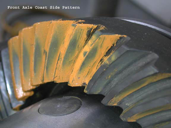
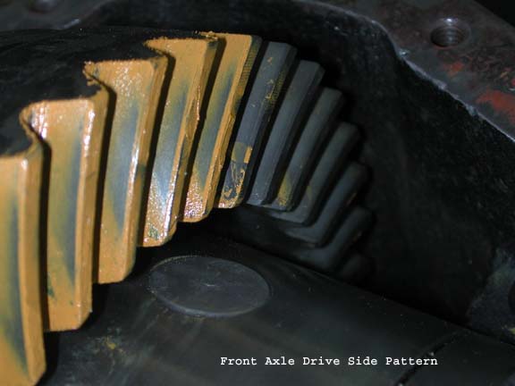
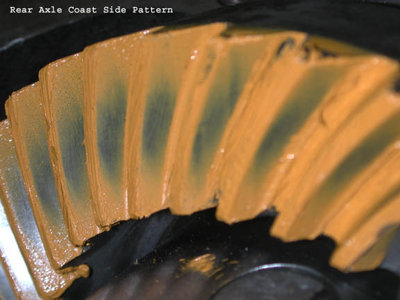
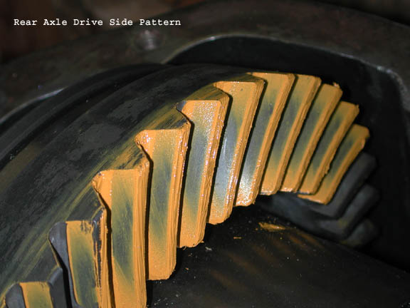
Even though pinion depth and backlash can be measured with a
precision of a few thousands of an inch, and the nominal conditions described
above can be met, the final adjustments in setting up gears requires analysis
of the actual contact between the teeth of the ring and pinion gears as determined
by a gear marking compound. This is a thick paste that is spread on the gears
and when the gears are turned leaves a pattern that indicates the true nature
of the contact between the teeth both on the drive and coast sides. The patterns
of the Truggy gears are shown below. The near centered contact pattern indicates
reasonable settings for both pinion depth and backlash of the new 5.86 gear
sets.
LOCKERS
 I
am a big fan of selectable lockers and have had pretty good performance out
of ARB lockers in Toyota differentials. This was the first I had installed in
a Dana differential. For the Dana differentials, the ARB uses a narrower carrier
bearing and makes up for that with the air input ring. The hardest part of the
installation is again getting the backlash set properly because of the fact
that the shims are positioned between the air input ring and the differential
housing. You can also notice that a hole or slot needs to be machined into the
bearing cap for the air line. As in alll ARB installations, a hole must also
be drilled in the housing for the air line fittings. The air line is an especially
tight fit with the OEM diff cover. The aluminum aftermarket covers provide additional
room as well as additional support for the bearing covers.
I
am a big fan of selectable lockers and have had pretty good performance out
of ARB lockers in Toyota differentials. This was the first I had installed in
a Dana differential. For the Dana differentials, the ARB uses a narrower carrier
bearing and makes up for that with the air input ring. The hardest part of the
installation is again getting the backlash set properly because of the fact
that the shims are positioned between the air input ring and the differential
housing. You can also notice that a hole or slot needs to be machined into the
bearing cap for the air line. As in alll ARB installations, a hole must also
be drilled in the housing for the air line fittings. The air line is an especially
tight fit with the OEM diff cover. The aluminum aftermarket covers provide additional
room as well as additional support for the bearing covers.
Part Two: Dana 60HD Rear Axle
The rear axle assembly is based on a Dana 60HD housing. Dana
60 rear axles have been used in a wide variety of domestic trucks and vans over
the past 30+ years. They have appeared in both full floater and semi-floater
(C-clip)designs and with 5, 6 and 8-lug hubs. All are characterized by a 10.5"
ring gear. In terms of offroad use, the most critical aspect of the D60 rear
axle is the size and spline count of the axle shafts. The OEM shafts and corresponding
side gears in the carrier assembly range from 1xx", 19-spline to 1.5",
35-spline units. By far the largest number of D60 rears found in Ford, GM and
Chrysler vans and trucks are full floaters with axle shafts that are 1.3"
in diameter with 30 splines at the differential end. There are considerably
fewer 35-spline, semi-floater axles that were used in Ford Vans. The rarest
of the OEM applications is a full floater with 1.5" diameter, 35-spline
axle shafts. Aftermarket axle assemblies from well respected companies such
as Currie and Dynatrac utilize the 1.5", 35-spline axle shafts, and these
are widely used in hard-core recreational and competition rigs.
There is much confusion and even uncertainty regarding the very
existence of the OEM 35-spline D60 rear full floater axles and/or housings.
The ARB application chart which many take to be gospel implies that many domestic
trucks came with these big axles. In reality, nearly all the trucks listed in
compilations such as the ARB one have 30-spline axles. The larger 35-spline
axles are much more rare in OEM applications.
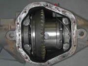
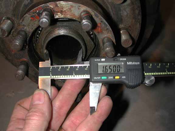
 To
my knowledge, all of the 35-spline OEM axles came in axle housings designated
by Dana/Spicer as Heavy Duty axles. These D60HD housings have
several features that set them apart from the standard D60 full floating axle
housing. The most significant difference is a larger bore on the spindle. While
the standard D60 spindle has an inner diameter of 1.407", the D60HD spindle
i.d. is 1.650", thus allowing use of the larger 1.5" diameter axle
shafts. The HD spindle has the same o.d. as the standard D60 (o.d. = 1.980).Options
for modifying the normal D60 to accomodate the big axles include boring out
the existing spindle to a larger diameter, or cutting off the spindles and replacing
them with either D70 or Ford 9" spindles. Obviously, finding one of the
D60HD axle housings with the big spindles has many advantages. Even if the axle
assembly does not have the big axle shafts, the large-bore spindles allow for
aftermarket 35-spline shafts. The housing in the Truggy came with no axles,
and in fact I first recognized it in the junk yard by observing the large bore
on the spindles.
To
my knowledge, all of the 35-spline OEM axles came in axle housings designated
by Dana/Spicer as Heavy Duty axles. These D60HD housings have
several features that set them apart from the standard D60 full floating axle
housing. The most significant difference is a larger bore on the spindle. While
the standard D60 spindle has an inner diameter of 1.407", the D60HD spindle
i.d. is 1.650", thus allowing use of the larger 1.5" diameter axle
shafts. The HD spindle has the same o.d. as the standard D60 (o.d. = 1.980).Options
for modifying the normal D60 to accomodate the big axles include boring out
the existing spindle to a larger diameter, or cutting off the spindles and replacing
them with either D70 or Ford 9" spindles. Obviously, finding one of the
D60HD axle housings with the big spindles has many advantages. Even if the axle
assembly does not have the big axle shafts, the large-bore spindles allow for
aftermarket 35-spline shafts. The housing in the Truggy came with no axles,
and in fact I first recognized it in the junk yard by observing the large bore
on the spindles.
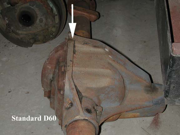
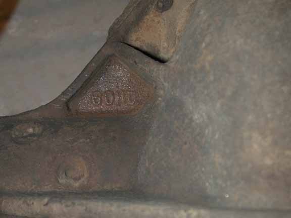
Three features of the D60HD housings are helpful in identifying
the units in a salvage yard. First, relative to the standard D60, the HD model
has distinctive double ribbing on the top of the cast center section. Secondly,
the HD housings have a main horizontal rib on the front of the center section
containing casting marks consisting of "60HD". Finally,
the D60HD housings are characterized by a very wide hub and drum brake assembly.
The dimensions of the HD spindle, hub and brakes are the same as the successor
to the D60HD, namely the Dana 70. Over the past three years, I have seen five
of these housings and have purchased two of them for an average price of $200.
Good investments in my book.
For the Truggy project, another big advantage of the D60HD axle
housing is that the width of the assembly based on wheel mounting surfaces is
65". As described in Part I above, the front D60 in the Truggy was narrowed
to a WMS width of 64.5". Thus, no narrowing of the rear axle housing was
required.
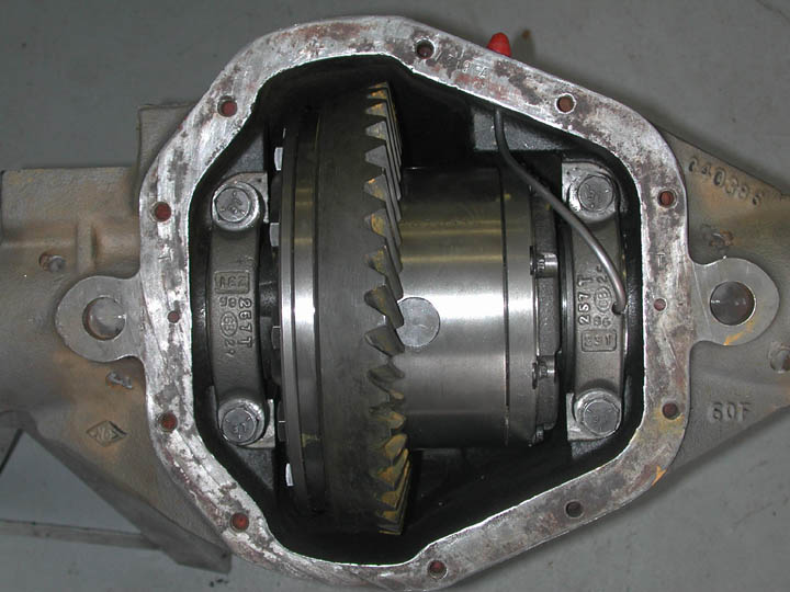
The major upgrades to the rear axle assembly include custom
1.5" diameter, 35-spline axle shafts from Dutchman Motorsports, 5.86:1
ring and pinion gears from Dana/Spicer and ARB air lockers. Installation of
the gears and lockers was done in the same manner as described above for the
front axle.
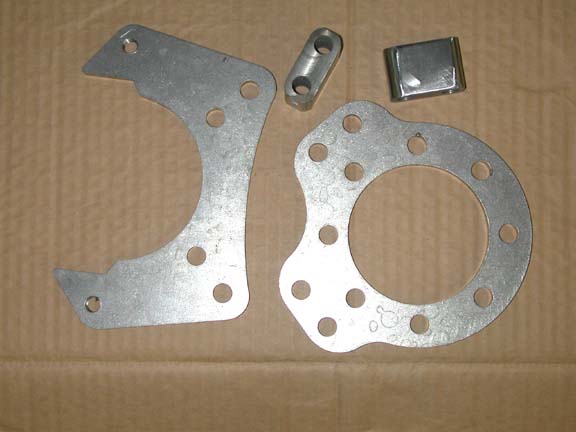
Rear Disc Cutting Brakes
As shown in the right image above another feature of the D60HD
axles are very large drum brakes and hubs. While these were undoubtedly powerful
brakes in their time, upgrade to disc brakes with individual wheel line locks
was desired for the project vehicle. Disc brake conversions are common for 4WD
rigs. The conversion involves three components: 1) disc brake rotors to replace
the drums fitting over the wheel hubs; 2) disc brake calipers to replace drum
brake shoes; and 3) a bracket to position and hold the calipers onto the rotor.
Because of the wide range of vehicles and configurations (full and semi floaters,
5, 6 and 8 lug hubs and normal versus wide brake drums and hubs) there is no
single bolt-on kit for the D60 rear axle. While the bolt pattern of the axle
flange that separates the axle tube from the spindle is the same on all D60
axles, the big difference between the various applications is the width of the
brake drums. For disc conversions this translates to the horizontal distance
between the outer surface of the axle housing flange and the center of the rotor
or caliper. In designing the brackets for the wide-brake conversion, I elected
to follow the lead of TSM and make brackets that would allow different brake
widths. In order to accomplish this the brackets consist of three components:
1) an inner bracket that bolts to the outer surface of the axle housing flange;
2) an outer bracket that bolts to the disc brake caliper and 3) spacer blocks
that mate the inner and outer brackets and correctly position the caliper on
the rotor. I designed the two 0.375" thick brackets with an AutoCad-like
program known as Vellum 3-D and had the brackets laser cut by Pneu-Con Systems
of Bend, OR. The spacer blocks I made on my milling machine. For the D60HD housings,
the required spacers are a whopping 1.34"thick , reflecting the size of
the original big drum brakes.
Popular disc brake assemblies for conversions basically come
in three sizes: the small units used on rear axles from cars such as the Monte
Carlo or El Dorado; intermediate sized front disc brakes from 3/4 ton pickups
and the big disc brake assemblies found on 1-ton trucks (such as the front Truggy
axle). For rear 8-lug hubs, the only real option is the intermediate-sized units.
The rotors and calipers selected for this project are listed in the table below.
 The
section on gear boxes describes how I modified
the NP205 transfer case to allow the rear output to be shifted into neutral
while the front remains in either low or hi range. With the rear output of the
NP205 in neutral and the rear ARB unlocked, each rear wheel is free to turn,
or not turn, independently. If each rear wheel/brake is equipped with
a line lock ( a valve in the brake line that locks the hydraulic pressure in
the line leading to the caliper after the brake pedal has been released. Line
lock technology has been perfected by the drag racing community where the front
wheels are locked while the rears spin up before green light. For the Truggy,
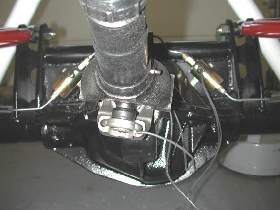
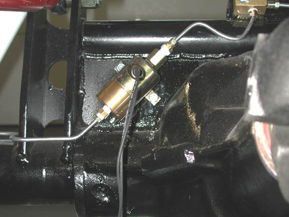
I use two electric Biondo Racing line locks, shown in the image to the right.
A more detailed image of one of the line locks is shown HERE.Operation
of the cutting brakes is as follows: Say you need to turn sharply to the left
-- the steps include disengaging the rear ARB, shifting the rear output of the
NP205 to neutral, pressing the brake pedal, engaging the left line lock (thus
locking the left wheel), releasing the brake pedal (Thus freeing all wheels
except the line locked left rear to turn) and finally driving through the turn
with the rig pivoting around the left rear wheel. Pictures of the cutting brake
system will be forthcoming as soon as I decide where to mount the two switches
for the line locks.
The
section on gear boxes describes how I modified
the NP205 transfer case to allow the rear output to be shifted into neutral
while the front remains in either low or hi range. With the rear output of the
NP205 in neutral and the rear ARB unlocked, each rear wheel is free to turn,
or not turn, independently. If each rear wheel/brake is equipped with
a line lock ( a valve in the brake line that locks the hydraulic pressure in
the line leading to the caliper after the brake pedal has been released. Line
lock technology has been perfected by the drag racing community where the front
wheels are locked while the rears spin up before green light. For the Truggy,
I use two electric Biondo Racing line locks, shown in the image to the right.
A more detailed image of one of the line locks is shown HERE.Operation
of the cutting brakes is as follows: Say you need to turn sharply to the left
-- the steps include disengaging the rear ARB, shifting the rear output of the
NP205 to neutral, pressing the brake pedal, engaging the left line lock (thus
locking the left wheel), releasing the brake pedal (Thus freeing all wheels
except the line locked left rear to turn) and finally driving through the turn
with the rig pivoting around the left rear wheel. Pictures of the cutting brake
system will be forthcoming as soon as I decide where to mount the two switches
for the line locks.
 The
image to the left shows the passenger's side of the D60. This axle came out
of a 1987 Chevy 1-ton (K-30) truck. It came withn 3.54 gears, 1.5" 35-spline
inner axle shafts and 1.3" 30-spline outer stub axles. Notice the passenger's
side spring perch that is machined into the center section. The axle components
outboard of the axle tube end/king pin/knuckle include the 1) outer knuckle
housing with steering arm, 2) brake backing plate and hub assembly. Removal
involves working from the outside to the knuckle. First remove the lock-out
hubs (Warn in my case), wheel bearing lock nut, lock ring and the wheel bearing
adjusting nut. This allows the hub and brake rotor be removed from the spindle.
With the hub removed, the spindle can next be removed by simply unbolting it
from the knuckle housing. Finally the outer knuckle housing can be removed from
the king pin assembly by removal of the steering arm and the bearing caps. The
two pictures below show the axle housing first with the hub and rotor removed
and next with the spindle removed.
The
image to the left shows the passenger's side of the D60. This axle came out
of a 1987 Chevy 1-ton (K-30) truck. It came withn 3.54 gears, 1.5" 35-spline
inner axle shafts and 1.3" 30-spline outer stub axles. Notice the passenger's
side spring perch that is machined into the center section. The axle components
outboard of the axle tube end/king pin/knuckle include the 1) outer knuckle
housing with steering arm, 2) brake backing plate and hub assembly. Removal
involves working from the outside to the knuckle. First remove the lock-out
hubs (Warn in my case), wheel bearing lock nut, lock ring and the wheel bearing
adjusting nut. This allows the hub and brake rotor be removed from the spindle.
With the hub removed, the spindle can next be removed by simply unbolting it
from the knuckle housing. Finally the outer knuckle housing can be removed from
the king pin assembly by removal of the steering arm and the bearing caps. The
two pictures below show the axle housing first with the hub and rotor removed
and next with the spindle removed. 


