 The
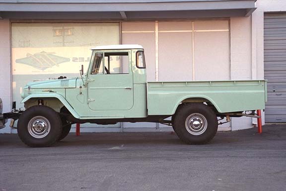
stock FJ45 long-wheel-base (LWB) truck has a 116" wheelbase as well as
a considerable amount of the box and frame positioned aft of the rear axle.
In terms of designing a rock crawler, the extended box and frame results in
a completely unacceptable departure angle. Furthermore, the wheelbase is too
long for the tight obstacles typically found in the most challenging of trails
and competitions. For these reasons the decision was made to both shorten the
frame (and box) and reduce the wheelbase. Before you criticize me for cutting
up this fine truck, please remember that it's twin and tow rig will retain most
of the stock appearance.
The
stock FJ45 long-wheel-base (LWB) truck has a 116" wheelbase as well as
a considerable amount of the box and frame positioned aft of the rear axle.
In terms of designing a rock crawler, the extended box and frame results in
a completely unacceptable departure angle. Furthermore, the wheelbase is too
long for the tight obstacles typically found in the most challenging of trails
and competitions. For these reasons the decision was made to both shorten the
frame (and box) and reduce the wheelbase. Before you criticize me for cutting
up this fine truck, please remember that it's twin and tow rig will retain most
of the stock appearance.
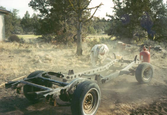 Before
doing any work on the frame, all brackets and mounts were removed and the entire
frame was sandblasted. I used a 100 lb.capacity, Harbor Freight, portable sand
blaster. My shop compressor puts out 30 cfm at 175 psi. This made relatively
quick, but still very dirty work. The end result is a clean frame that is both
easier to work on, and one that will be much easier to paint when all modifications
are completed.
Before
doing any work on the frame, all brackets and mounts were removed and the entire
frame was sandblasted. I used a 100 lb.capacity, Harbor Freight, portable sand
blaster. My shop compressor puts out 30 cfm at 175 psi. This made relatively
quick, but still very dirty work. The end result is a clean frame that is both
easier to work on, and one that will be much easier to paint when all modifications
are completed.
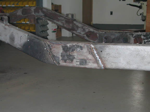
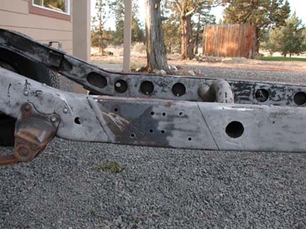 Interestingly,
when Toyota made the LWB frames, they elected to start with the SWB frame and
then increase its length by adding a 12" insert into the primary C-channel
frame. The SWB frame (104" wheel base) was cut on a diagonal, the insert
welded in and then a sleeve was welded onto the top, bottom and outside of the
insert. The image to the left shows the stock frame with the sleeve removed.
The original welding was done from the inside of the frame and did not penetrate
through the entire frame. The lines you see in the image are the junctions that
were not filled by the welding process. Fortunately the sleeve and the inner
frame insert (with the circles cut into it) provided sufficient strength for
the less-than-completely welded frame.
Interestingly,
when Toyota made the LWB frames, they elected to start with the SWB frame and
then increase its length by adding a 12" insert into the primary C-channel
frame. The SWB frame (104" wheel base) was cut on a diagonal, the insert
welded in and then a sleeve was welded onto the top, bottom and outside of the
insert. The image to the left shows the stock frame with the sleeve removed.
The original welding was done from the inside of the frame and did not penetrate
through the entire frame. The lines you see in the image are the junctions that
were not filled by the welding process. Fortunately the sleeve and the inner
frame insert (with the circles cut into it) provided sufficient strength for
the less-than-completely welded frame.
I made the decision to aim for a nominal wheel base of 106". As will be documented elsewhere in this website, the drivetrain on this this truggy (SM465-NP203-NP205) is long -- too long for a swb rig like an FJ40. I determined that a wheel base in the range of 105-106" would be optimal. I therefore elected to remove 10" of the original 12" insert. I could have simply removed the entire 12" insert, but I wanted a few extra inches in this straight portion of the frame to mount my 1/4 elliptical control arm hangers.
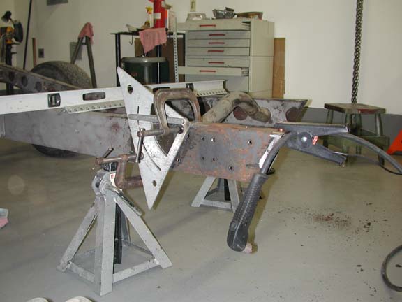 I
don't like making vertical cuts or welds on a frame, so I chose to follow Toyota's
lead and make my cuts on a diagonal. The image to the right shows the jig I
used to make the parallel cuts. I used a carpenter's rafter/joist triangle to
set the angle and as a guide for the plasma torch which was used to made the
cuts. I would not make these cuts with anything but a plasma torch. The procedure
was quick and precise.
I
don't like making vertical cuts or welds on a frame, so I chose to follow Toyota's
lead and make my cuts on a diagonal. The image to the right shows the jig I
used to make the parallel cuts. I used a carpenter's rafter/joist triangle to
set the angle and as a guide for the plasma torch which was used to made the
cuts. I would not make these cuts with anything but a plasma torch. The procedure
was quick and precise.
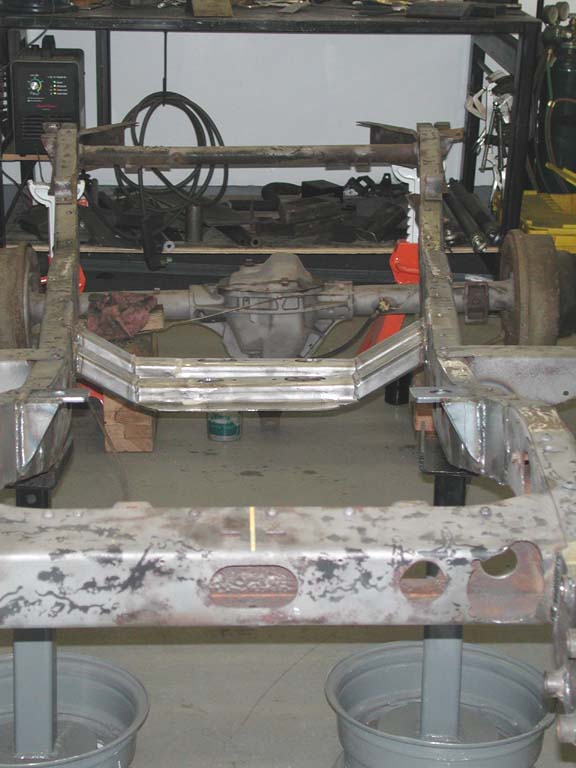
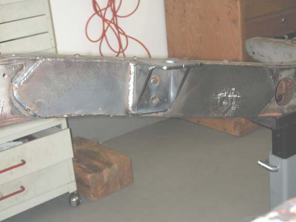
 The
image to the left shows the shortened and reassembled frame with a slightly
shorter sleeve welded onto the top, bottom and outside of the primary frame.
Use of diagonal cuts and flat plates clamped onto the bottom and sides of the
frame allowed for proper fit and orientation of the two parts before welding
together. It was nevertheless one of those measure 100 times and then
weld moments. I also removed the mis-matched section of the inner frame
insert (with the circles cut into it) and replaced that with a new insert. You
will notice that the frame-shortening procedure resulted in removal of the round
frame crossmember located aft of the transfer case. With the centered-output
NP205 transfer case, this crossmember would not fit anyhow. At this time, it
is not certain whether another solid crossmember will be included or not.
The
image to the left shows the shortened and reassembled frame with a slightly
shorter sleeve welded onto the top, bottom and outside of the primary frame.
Use of diagonal cuts and flat plates clamped onto the bottom and sides of the
frame allowed for proper fit and orientation of the two parts before welding
together. It was nevertheless one of those measure 100 times and then
weld moments. I also removed the mis-matched section of the inner frame
insert (with the circles cut into it) and replaced that with a new insert. You
will notice that the frame-shortening procedure resulted in removal of the round
frame crossmember located aft of the transfer case. With the centered-output
NP205 transfer case, this crossmember would not fit anyhow. At this time, it
is not certain whether another solid crossmember will be included or not.
This particular area of the frame is especially important in that it serves as the mounting location for the rear suspension. It must be strong. In the stock configuration, the rear spring hanger is located just aft of the sleeve and the bend in the frame.
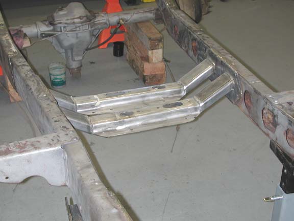
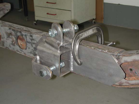 With
the 1/4 elliptical rear suspension designed and built for this truck, this area
of the frame will host both the spring hanger and the mounting points for the
4 control arms. The image to the right shows one control-arm hanger clamped
onto the inside of the frame in its approximate position (the exact position
will be fixed when the entire drivetrain and rear axle is positioned). The hanger
proper is welded onto a 14"-long scab pleate that will be welded to the
inside of the frame. The spring hanger will be bolted on to the frame in the
area aft of the C-clamp. This area of the frame will clearly be one of the strongest
parts of the entire frame.
With
the 1/4 elliptical rear suspension designed and built for this truck, this area
of the frame will host both the spring hanger and the mounting points for the
4 control arms. The image to the right shows one control-arm hanger clamped
onto the inside of the frame in its approximate position (the exact position
will be fixed when the entire drivetrain and rear axle is positioned). The hanger
proper is welded onto a 14"-long scab pleate that will be welded to the
inside of the frame. The spring hanger will be bolted on to the frame in the
area aft of the C-clamp. This area of the frame will clearly be one of the strongest
parts of the entire frame.
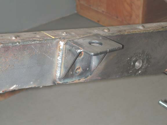
Front Frame Horns
As explained in the suspension section (forthcoming), in an attempt to match the articulation provided by the front with that of the 1/4 elliptical rear suspension, I chose to use longer-than-stock front springs. The stock FJ45 springs are the same length as the FJ40 and FJ55 springs (42" in length measured along the spring). Originally, I considered using the extremely long (49.8") rear springs from the FJ45. I decided that these springs are both too long and too stiff for use in the front. I elected finally to use a set of aftermarket FJ60 rear springs that a friend gave me after converting to OME springs. These are seven-leaf springs, with tapered ends and teflon pads. They are 46" in length.
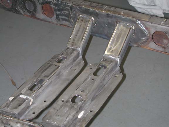
In order to reatin the location of the front axle, use of these springs requires that the front frame horns be extended by 3". The photos below (forthcoming) show both the passenger and driver side frame horns after being extended. Notice that the frame extensions have been incorporated with the scab plates for the power steering box.
Engine and Transmission Mounts
 As
is the case with my FJ40, the Vortec engine is mounted to the frame with Advance
Adapter motor mounts. What is slightly different in this application is that
I used long scabplates to strengthen the frame
rails on either side of the motor mounts. The scab plates extend far enough
to the rear to also incorporate the thru-the-frame mounting tubes for the spring
shackles. The angle of the motor mount is such that the drivetrain is essentially
horizontal and the transmission, and transfer cases are all above the bottom
of the frame.
As
is the case with my FJ40, the Vortec engine is mounted to the frame with Advance
Adapter motor mounts. What is slightly different in this application is that
I used long scabplates to strengthen the frame
rails on either side of the motor mounts. The scab plates extend far enough
to the rear to also incorporate the thru-the-frame mounting tubes for the spring
shackles. The angle of the motor mount is such that the drivetrain is essentially
horizontal and the transmission, and transfer cases are all above the bottom
of the frame.
The SM465, NP203 range box and NP205 transfer case constitute a strong but also a heavy set of gearboxes. The combination of weight and considerable torque (up to 8500 ft. lbs. on the output shaft of the NP205 in double-low range) requires a strong mounting system for the gear boxes. Since each of the two adapters is designed to serve as a mounting point, I elected to use them both in a double crossmember arrangement. My original plan was to use two of the stock crossmember transmission mounts used in GM 4WD trucks equipped with the SM465 transmission. These crossmembers, although ideal for mounting to the adapters, dropped the gearboxes more than 4" below the level of the bottom of the frame and also were too wide for the FJ frame. I ended up cutting the center section out of each of the GM crossmembers and welding them to 4 x 1.5' rectangular tubing with a 3/16" wall thickness. The ends of the rectangular tubing were cut at 45 degrees to provide an appropriate amount of drop from the center of the frame rails. I use aftermarket "C-type" poly transmission mounts between the adapter housings and the crossmembers. Pictures of the crossmember mounts are shown below.
 |
 |
 |