Steering
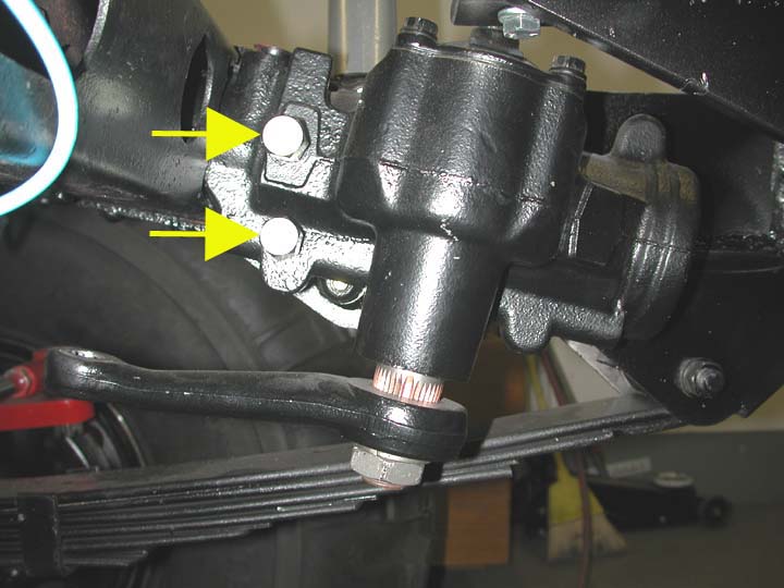
 Box:
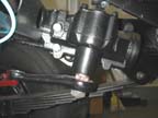
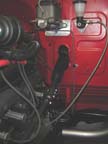
The steering gear box is a four-bolt, four-turn Saginaw Model
800 box. The box is mounted in the traditional fashion by welding scab plates
to the inside of the frame rails. For additional strength, I also welded a scab
plate on the outside of the frame on the driver's side. Bolt holes through the
frame are sleeved. The box was modified to allow for hydro-assist steering by
machining hydraulic ports into the fluid channel ways in the Saginaw box. The
fittings for the hoses running between the gear box and the hydraulic ram are
indicated by the arrows in the image to the left.
Box:
The steering gear box is a four-bolt, four-turn Saginaw Model
800 box. The box is mounted in the traditional fashion by welding scab plates
to the inside of the frame rails. For additional strength, I also welded a scab
plate on the outside of the frame on the driver's side. Bolt holes through the
frame are sleeved. The box was modified to allow for hydro-assist steering by
machining hydraulic ports into the fluid channel ways in the Saginaw box. The
fittings for the hoses running between the gear box and the hydraulic ram are
indicated by the arrows in the image to the left.
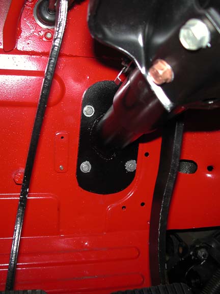
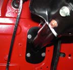 Column:
The steering column is a GM tilt column from a 1974 Camero/Firebird. These
columns are relatively easy to adapt to a Land Cruiser. The fitting on the column
support arm can be modified without much effort so that it bolts to the bottom
of the dash, just like the OEM column. The second modification that is required
is to fabricate and weld a plate onto the steering column housing that allows
it to be bolted to the firewall of the Cruiser (right image). The older style
tub with the elongated firewall hole makes this an easy project. The GM column
also has all of the wiring and switches that could be incorporated if desired.
Since the truggy has no windshield wipers or turn signals, I removed all of
the wiring except for the ignition switch.
Column:
The steering column is a GM tilt column from a 1974 Camero/Firebird. These
columns are relatively easy to adapt to a Land Cruiser. The fitting on the column
support arm can be modified without much effort so that it bolts to the bottom
of the dash, just like the OEM column. The second modification that is required
is to fabricate and weld a plate onto the steering column housing that allows
it to be bolted to the firewall of the Cruiser (right image). The older style
tub with the elongated firewall hole makes this an easy project. The GM column
also has all of the wiring and switches that could be incorporated if desired.
Since the truggy has no windshield wipers or turn signals, I removed all of
the wiring except for the ignition switch.
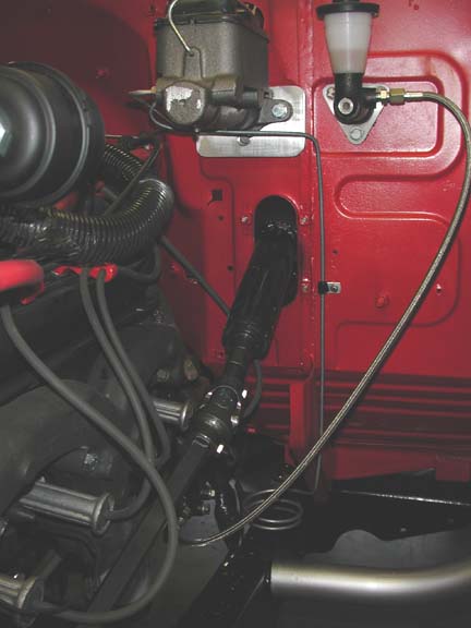
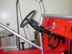
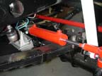
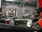 Shaft:
The steering shaft is a 3/4" Borgeson DD shaft with the Borgeson needle-bearing
u-joints. The image to the left shows the end of the Camero steering column
sticking through the firewall and its connection to the Borgeson shaft. I welded
a solid piece of .750" DD shaft onto the end of the GM column. This piece
then mates into one end of the upper u-joint. As shown in the images, the steering
shaft nicely clears the exhaust manifolds and power steering pump (not shown).
The lower u-joint connects the DD shaft to the splined input shaft of the Saginaw
800-series gear box. Also visible on the firewall are the master cylinders for
the clutch (right) and brakes. The brake master is a non-boosted master from
a Ford F350.
Shaft:
The steering shaft is a 3/4" Borgeson DD shaft with the Borgeson needle-bearing
u-joints. The image to the left shows the end of the Camero steering column
sticking through the firewall and its connection to the Borgeson shaft. I welded
a solid piece of .750" DD shaft onto the end of the GM column. This piece
then mates into one end of the upper u-joint. As shown in the images, the steering
shaft nicely clears the exhaust manifolds and power steering pump (not shown).
The lower u-joint connects the DD shaft to the splined input shaft of the Saginaw
800-series gear box. Also visible on the firewall are the master cylinders for
the clutch (right) and brakes. The brake master is a non-boosted master from
a Ford F350.
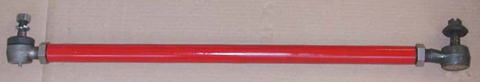
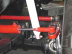
The tie rod and drag link are made from 1.375"
DOM tube with a 0.375" wall thickness. All tie rod ends are one-ton units
with a 1.0" threaded shank. I cut left- and right-hand threads in the DOM
tube (no weld inserts used) and also made the stainless steel jam nuts from
hex rod.
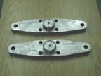
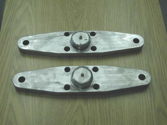
 Steering
Arms: The Dana 60 front axle uses a king-pin type
of knuckle that allows for a custom hi-steer type of arm to be bolted on top
of the knuckle assembly. With the big tires, I wanted to design a steering system
that would spread the forces involved with steering more evenly between both
knuckles, the drag link and the tie rod. To achieve this goal I made a pair
of double steering arms. These arms place the tie rod behind the axle, out of
the way of rocks and other obstacles. The front half of the passenger's side
arm is connected to the drag link from the power steering box and the front
half of the driver's side arm is connected to the hydraulic ram.
Steering
Arms: The Dana 60 front axle uses a king-pin type
of knuckle that allows for a custom hi-steer type of arm to be bolted on top
of the knuckle assembly. With the big tires, I wanted to design a steering system
that would spread the forces involved with steering more evenly between both
knuckles, the drag link and the tie rod. To achieve this goal I made a pair
of double steering arms. These arms place the tie rod behind the axle, out of
the way of rocks and other obstacles. The front half of the passenger's side
arm is connected to the drag link from the power steering box and the front
half of the driver's side arm is connected to the hydraulic ram.

 With
this arrangement during a turn to the left, the drag link pushes on the passenger's
arm while the hydraulic ram pulls on the driver's side arm. The arms themselves
are made from 1" thick T-1 steel. The pieces were rough cut with a CNC
flame torch and then finished on my milling machine. The arms are 14" long
and 3.25" wide. The king-pin to TRE-center distance is 6.5" -- the
same as the length of the Pitman arm I use on the Saginaw gear box. Since this
is strictly an off-road rig and the differentials will be locked most of the
time, no effort was made to produce correct Ackerman geometry by making the
rear of the arms narrower than the front. A 2.125" hole was milled in the
center of each arm and the king-pin cap was welded into the arm. The arms are
bolted to the knuckles with 4 studs. I tapered the top end of each hole in the
arm to allow the use of tapered (lug-nut style) nuts on each of the studs. The
holes in the end of each arm were drilled and then taperd to fit the one-ton
tie rod ends used on the tie rod, drag link and ram end.
With
this arrangement during a turn to the left, the drag link pushes on the passenger's
arm while the hydraulic ram pulls on the driver's side arm. The arms themselves
are made from 1" thick T-1 steel. The pieces were rough cut with a CNC
flame torch and then finished on my milling machine. The arms are 14" long
and 3.25" wide. The king-pin to TRE-center distance is 6.5" -- the
same as the length of the Pitman arm I use on the Saginaw gear box. Since this
is strictly an off-road rig and the differentials will be locked most of the
time, no effort was made to produce correct Ackerman geometry by making the
rear of the arms narrower than the front. A 2.125" hole was milled in the
center of each arm and the king-pin cap was welded into the arm. The arms are
bolted to the knuckles with 4 studs. I tapered the top end of each hole in the
arm to allow the use of tapered (lug-nut style) nuts on each of the studs. The
holes in the end of each arm were drilled and then taperd to fit the one-ton
tie rod ends used on the tie rod, drag link and ram end.
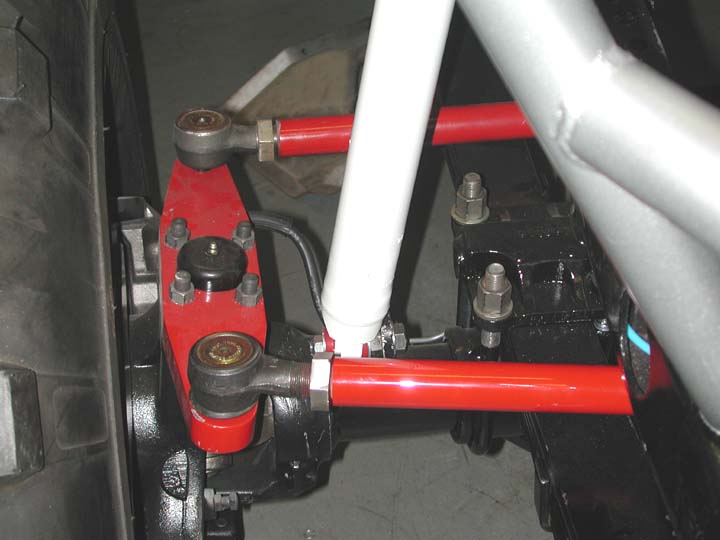
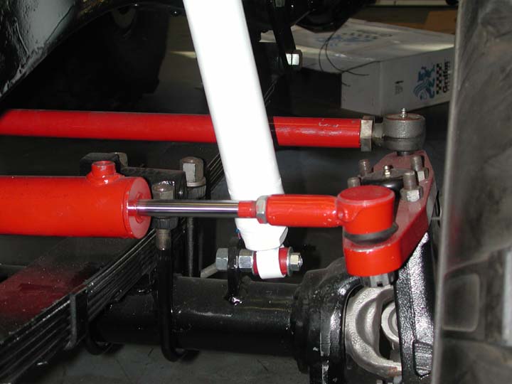
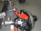
 Hydraulic
Ram: The single-ended, hydraulic ram is shown to the left. It is a 2"
ram with an 8" stroke. It is mounted on each end with 3/4" heim joints.
The stationary end mounts to a mounting plate that bolts onto the top of the
Dana 60 axle housing. The tie rod is visible in the background.
Hydraulic
Ram: The single-ended, hydraulic ram is shown to the left. It is a 2"
ram with an 8" stroke. It is mounted on each end with 3/4" heim joints.
The stationary end mounts to a mounting plate that bolts onto the top of the
Dana 60 axle housing. The tie rod is visible in the background.
Pump, Reservoir and Cooling: The hydro-assisted
power steering setup obviously requires an increased volume of fluid in the
power steering system. Furthermore, compression in the hydraulic ram adds considerable
heat to the fluid. In order to address these issues, I added an external fluid
reservoir and a 2" x 24" frame-rail cooler. Pictures of these items
will be forthcoming. The pump itself is the OEM Saginaw pump on the Vortec.
The flow rate through the pump was increased by the modification
developed by Matt Hodges of West Texas Off Road. I did not attempt to increase
the pressure output of the pump.
 Box:
The steering gear box is a four-bolt, four-turn Saginaw Model
800 box. The box is mounted in the traditional fashion by welding scab plates
to the inside of the frame rails. For additional strength, I also welded a scab
plate on the outside of the frame on the driver's side. Bolt holes through the
frame are sleeved. The box was modified to allow for hydro-assist steering by
machining hydraulic ports into the fluid channel ways in the Saginaw box. The
fittings for the hoses running between the gear box and the hydraulic ram are
indicated by the arrows in the image to the left.
Box:
The steering gear box is a four-bolt, four-turn Saginaw Model
800 box. The box is mounted in the traditional fashion by welding scab plates
to the inside of the frame rails. For additional strength, I also welded a scab
plate on the outside of the frame on the driver's side. Bolt holes through the
frame are sleeved. The box was modified to allow for hydro-assist steering by
machining hydraulic ports into the fluid channel ways in the Saginaw box. The
fittings for the hoses running between the gear box and the hydraulic ram are
indicated by the arrows in the image to the left.