SUSPENSION
The goals for the truggy's suspension included
providing a stable, affordable and strong system that would allow for considerable
flex and articulation. I couldn't affort to spend thousands of dollars for a
coil-over suspension, but at the same time, I did not want to be limited to
to the articulation allowed by traditional leaf spring suspensions.
FRONT SUSPENSION
 The
front suspension consists of a more-or-less traditional spring-over axle suspension
combined with a shackle reversal. There are, however, several minor twists that
will provide increased flex and articulation. The first of these twists are
the springs themselves. They are the rear springs from an FJ60 wagon. The spring
packs contain 7 leaves and the individual leaves are tapered and include anti-friction
pads at each end. They were nearly flat when removed from the heavy wagon. The
advantage they have over stock FJ45 (or 40) springs is in their length -- 45.7"
compared to the stock FJ40/45 length of 42". For comparison, FJ55 springs
are 45.5 " in length.(For consistency, the lengths quoted here are taken
from Rob Mullen's Land Cruiser FAQ [http://www.off-road.com/tlc/faq/frame.html#HD_NM_3])
The longer spring, when used in conjuction with a long shackle allows for more
drop and hence better articulation. Another advantage is that the 60-series
springs used the larger spring eyes and bushings than those on the 40/45. Use
of the large spring eye with rubber bushings allows for more twist in the spring
relative to the spring pin, and hence more articulation. The rubber bushings
will wear out quicker than poly bushings, but who cares on a trail rig like
this .
The
front suspension consists of a more-or-less traditional spring-over axle suspension
combined with a shackle reversal. There are, however, several minor twists that
will provide increased flex and articulation. The first of these twists are
the springs themselves. They are the rear springs from an FJ60 wagon. The spring
packs contain 7 leaves and the individual leaves are tapered and include anti-friction
pads at each end. They were nearly flat when removed from the heavy wagon. The
advantage they have over stock FJ45 (or 40) springs is in their length -- 45.7"
compared to the stock FJ40/45 length of 42". For comparison, FJ55 springs
are 45.5 " in length.(For consistency, the lengths quoted here are taken
from Rob Mullen's Land Cruiser FAQ [http://www.off-road.com/tlc/faq/frame.html#HD_NM_3])
The longer spring, when used in conjuction with a long shackle allows for more
drop and hence better articulation. Another advantage is that the 60-series
springs used the larger spring eyes and bushings than those on the 40/45. Use
of the large spring eye with rubber bushings allows for more twist in the spring
relative to the spring pin, and hence more articulation. The rubber bushings
will wear out quicker than poly bushings, but who cares on a trail rig like
this .
The FJ60 series springs are like those used on
the 40 series (but unlike the FJ55s) in that the spring pin is off center. In
the original application, the short side of the spring pack is always oriented
toward the transfer case so as to reduce the effects of axle wrap and minimize
the amount of pinion rotation as the spring pack travels thru it's range of
motion. I have always believed in this philosophy and have never "flipped
spring packs" in order to increase the wheelbase. For the front axle, this
means that the short side of the spring should be at the rear toward the transfer
case. Since the springs originally came from the rear, I had to flip the spring
pack front to back in order to put the short side of the spring pack to the
rear when installed as the front springs. This also required that I re-drill
and flip the #2 leaf in order to put the military wrap at the front of the spring
pack. This arrangement places the springs with the short end of the pack toward
the transfer case and the military wrap at the front spring hanger.
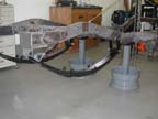
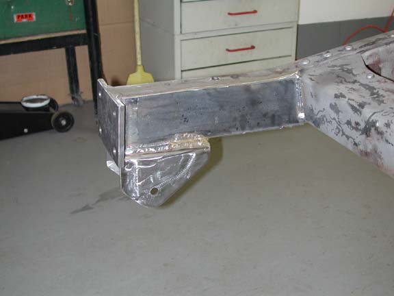
In order to place the axle in its original frame
position with the longer springs, I had to lengthen the front frame horns by
3". Furthermore, the longer springs combined with the angle that the frame
tilts downward in the area where the shackles would be mounted necessitated
that the front spring hanger be lowered 1.5" in order to keep the spring
pack approximately level at the final ride configuration. In order to accomplish
all of this, I made my own front spring hangers. I roughly copied the design
used by Toyota so that I could use the stock FJ60 spring pins. I started with
4x6" rectangular box tube with a .250" wall thickness. I then narrowed
the box and milled it to the desired shape.
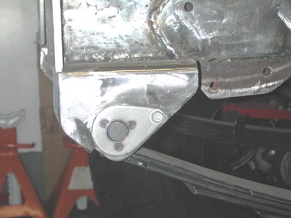
 The
mounting of the shackle at the rear of the springs employs a "through the
frame" approach. This approach is required owing to the slope of the frame
at the shackle mounting location. A mount welded onto the bottom of the frame
will tilt the spring back and hence the front pinion too far downward. Mounting
the upper shackle pin through the frame also allows for use of a longer shackle
which provides more movement for the spring. The location for the hole to be
drilled through the frame is determined by mounting in the front spring hanger
only the primary leaf from the pack. With sufficient weight on the frame, a
floor jack can be placed under this single leaf and when the jack is raised
the leaf compresses. I place a piece of .250" thick flat bar between the
rear spring eye and the bottom of the frame. As the leaf compresses the rear
spring eye pushes up against the flat bar and frame and then moves aft along
the frame as the leaf flattens. The maximum amount of movement (extension) is
achieved when the leaf is perfectly flat. Further compression causes the spring
to invert and the spring eye to begin moving forward. The location of the center
of the spring eye just before inversion is marked by the yellow line on the
frame. Given this point on the frame and the desired length of the shackle,
the location of the hole through the frame is easily determined. I cut a 1.25"
diameter hole through the frame and weld in a 1" o.d. tube with a 3/16"
wall thickness. Alignment is achieved by fitting a long 5/8" diameter rod
through both driver's and passenger's side holes and set perpendicular to the
frame. 5/8" bolts are used for the shackles.
The
mounting of the shackle at the rear of the springs employs a "through the
frame" approach. This approach is required owing to the slope of the frame
at the shackle mounting location. A mount welded onto the bottom of the frame
will tilt the spring back and hence the front pinion too far downward. Mounting
the upper shackle pin through the frame also allows for use of a longer shackle
which provides more movement for the spring. The location for the hole to be
drilled through the frame is determined by mounting in the front spring hanger
only the primary leaf from the pack. With sufficient weight on the frame, a
floor jack can be placed under this single leaf and when the jack is raised
the leaf compresses. I place a piece of .250" thick flat bar between the
rear spring eye and the bottom of the frame. As the leaf compresses the rear
spring eye pushes up against the flat bar and frame and then moves aft along
the frame as the leaf flattens. The maximum amount of movement (extension) is
achieved when the leaf is perfectly flat. Further compression causes the spring
to invert and the spring eye to begin moving forward. The location of the center
of the spring eye just before inversion is marked by the yellow line on the
frame. Given this point on the frame and the desired length of the shackle,
the location of the hole through the frame is easily determined. I cut a 1.25"
diameter hole through the frame and weld in a 1" o.d. tube with a 3/16"
wall thickness. Alignment is achieved by fitting a long 5/8" diameter rod
through both driver's and passenger's side holes and set perpendicular to the
frame. 5/8" bolts are used for the shackles.
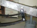
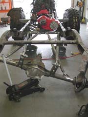
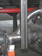
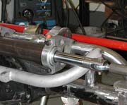
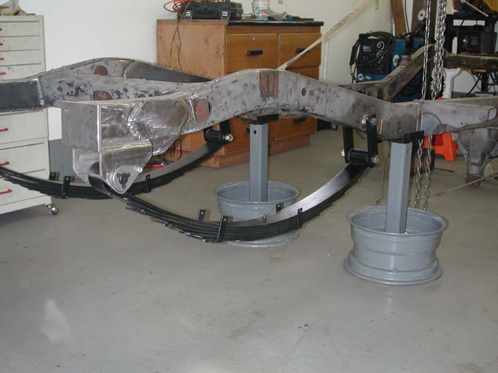
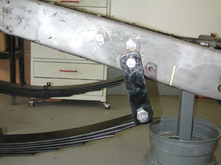
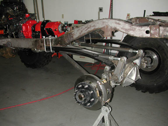
 Here
is a view of the shackle with the weight of the drivetrain and frame on the
springs.Currently the shackles are 5.5" in length between centers. The
additional weight of the body will result in further compression and an angle
on the shackle of very near to 45 degrees -- the optimal value for a leaf spring
suspension. I may need to lengthen the shackles, perhaps to 6.5", but want
to try out the existing ones first. Shocks are Rancho 9012 adjustable units.
Final placement of the shocks and towers will need to wait until I can cycle
the front suspension in order to determine the optimal amount of up-travel for
the suspension.
Here
is a view of the shackle with the weight of the drivetrain and frame on the
springs.Currently the shackles are 5.5" in length between centers. The
additional weight of the body will result in further compression and an angle
on the shackle of very near to 45 degrees -- the optimal value for a leaf spring
suspension. I may need to lengthen the shackles, perhaps to 6.5", but want
to try out the existing ones first. Shocks are Rancho 9012 adjustable units.
Final placement of the shocks and towers will need to wait until I can cycle
the front suspension in order to determine the optimal amount of up-travel for
the suspension.
REAR SUSPENSION
The rear suspension is a 4 link, 1/4 elliptical
design. It is the product of collaboration with Jason
Conover, co-owner of S&N Fab in
Stanwood, WA. Although a 1/4 elliptical suspension is is conceptually straightforward,
the performance of the suspension is critically dependent on the design and
geometry of the control arms or "links". Variation in the position,
angles and lengths of the links can result in undesirable features such as excessive
rear steer (a condition in which the rear axle "turns" when articulated)
or excessive anti-squat (a condition where the rear of the rig lifts upon power
and the axle wants to walk under the rig when climbing). S&N has been building
custom 1/4 elliiptical suspensions for several years and their design has proven
to be effective in several competition rock buggies. I contacted Jason in 2001
to inquire if he would be willing to build parts required for me to make a custom
suspension. He agreed and on a trip through Eugene to a rock crawling competition
last fall he dropped off the parts, including the links, hangers, heim joints
and shackles. Unfortunately the system Jason originally designed would not work
on the truggy. The doubler positions the NP205 right where the link hanger on
the passenger's side needs to go. The only options would be to A) increase the
wheelbase by 6" or B) move the hangers back and shorten the control arms
by 6". Neither option was acceptable, since there was no way I wanted to
end up with a 112" wheelbase and in Jason's experience the shorter links
would create unacceptable rear steer. So Jason came down to my shop in August
of 2002 and together we built a custom 1/4 eliptical suspension specifically
for the truggy.
In a normal leaf spring suspension, the leaf spring
pack serves to both locate the axle (attach it to the frame) and support the
sprung weight of the vehicle. A 1/4 elliptical spring consists of a regular
spring that has been cut in half and mounted upside down. One end of the half
spring is firmly attached to the frame while the other is attached to the axle
housing with a shackle. With this configuration the springs have no ability
to "locate" the axle. Control arms, or links, are thus necessary to
locate the axle fore and aft, prevent the axle from moving from side to side
and the pinion from rotating up or down. The geometry of the links determines
how much the axle can move and articulate. Link suspensions vary in both number
and geometry of the links. Some consist of 3 or 4 nearly parallel links and
a panhard bar to prevent side-to-side movement. The panhard bar can be eliminated
if two or more of the links are triangulated rather than parallel.
 The
truggy suspension consists of four triangulated links. The links were fabricated
from schedule 80 pipe and include large (1" diameter shaft) agriculture
heim joints on each end. They can be described as consisting of 1) a lower pair
of links that are triangulated from the centerline of the frame to the outer
front portion of the axle housing and 2) an upper pair of links that are slightly
triangulated from the inside of the frame rails to the outermost edge of the
differential. These upper arms mount above the axle housing on 7" tall
brackets. The links are adjustable in their length and can be used, for example
to move the axle fore and aft or to rotate the pinion up or down. The upper
and lower links are of approximately equal lengths at 43" measured from
the centers of the Heim joints.
The
truggy suspension consists of four triangulated links. The links were fabricated
from schedule 80 pipe and include large (1" diameter shaft) agriculture
heim joints on each end. They can be described as consisting of 1) a lower pair
of links that are triangulated from the centerline of the frame to the outer
front portion of the axle housing and 2) an upper pair of links that are slightly
triangulated from the inside of the frame rails to the outermost edge of the
differential. These upper arms mount above the axle housing on 7" tall
brackets. The links are adjustable in their length and can be used, for example
to move the axle fore and aft or to rotate the pinion up or down. The upper
and lower links are of approximately equal lengths at 43" measured from
the centers of the Heim joints.
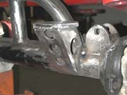
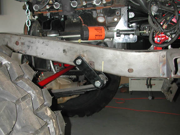
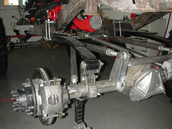
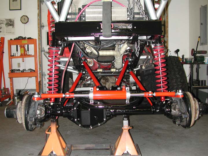
 The
links are attached to the frame by a crossmember welded to the bottom of the
frame and gusseted to the side of the frame. The crossmember is made from 2x4
rectangular box steel with a .250 wall thickness. Extending two inches below
the frame, the crossmember is the lowest point under the drivetrain, and will
also serve as the rear support for the skid plate. The image to the right gives
a good view of the crossmember, the front ends of the links and the heim joints
used to join them.
The
links are attached to the frame by a crossmember welded to the bottom of the
frame and gusseted to the side of the frame. The crossmember is made from 2x4
rectangular box steel with a .250 wall thickness. Extending two inches below
the frame, the crossmember is the lowest point under the drivetrain, and will
also serve as the rear support for the skid plate. The image to the right gives
a good view of the crossmember, the front ends of the links and the heim joints
used to join them.
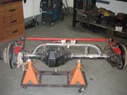
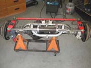
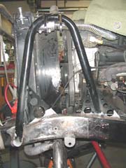
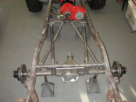
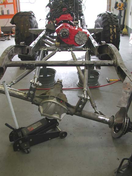
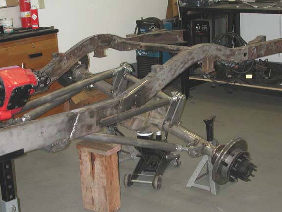
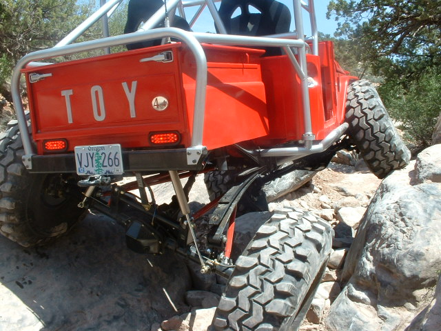
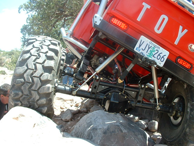
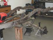 These
two images illustrate the range of motion allowed by the link system. Owing
to the geometry of the inks, at some point of artuculation the upper and lower
links will collide with each other. The images here show the axle housing at
the point of link convergence. At the inside of the frame, the vertical travel
allowed is almost 15 inches. Of course it is greater at the end of the axle.
At the maximum amount of movement, the rear steer is only 1/2 ". Also evident
in the image to the right is the fact that as the axle articulates it also swings
a bit from side-to-side. This is a useful feature since it moves the wheel being
compressed away from the frame, thus allowing more compression before the tire
might rub on the frame or body. Obviously, I don't want the links to actually
collide with each other. A combination of bumpstops and limiting straps will
be used to limit the suspension movement so as to prevent link damage. If I
decide that more movement is desirable, I will make a new set of upper links
with a slight bend in them that will allow for more articulation before the
links interfere with each other.
These
two images illustrate the range of motion allowed by the link system. Owing
to the geometry of the inks, at some point of artuculation the upper and lower
links will collide with each other. The images here show the axle housing at
the point of link convergence. At the inside of the frame, the vertical travel
allowed is almost 15 inches. Of course it is greater at the end of the axle.
At the maximum amount of movement, the rear steer is only 1/2 ". Also evident
in the image to the right is the fact that as the axle articulates it also swings
a bit from side-to-side. This is a useful feature since it moves the wheel being
compressed away from the frame, thus allowing more compression before the tire
might rub on the frame or body. Obviously, I don't want the links to actually
collide with each other. A combination of bumpstops and limiting straps will
be used to limit the suspension movement so as to prevent link damage. If I
decide that more movement is desirable, I will make a new set of upper links
with a slight bend in them that will allow for more articulation before the
links interfere with each other.
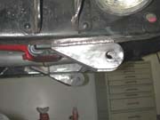
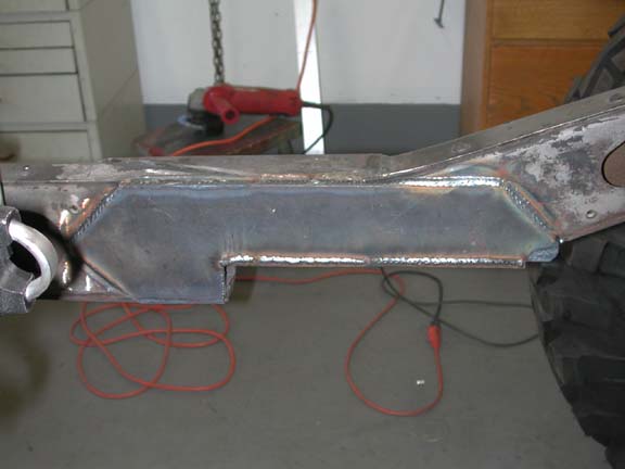
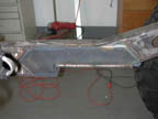 The
fixed end of the springs attach to the frame at the point where the frame begins
to angle up to clear the axles. In order to provide a flat surface and to tuck
the springs up high away from obstacles, I cut a notch in the frame as shown
in the image to the left. The notch includes a flat 3/16" plate welded
into the center of the frame with a hole in it cut for the centering pin of
the spring pack. A 3/16" thick scab plate was welded onto the inside of
the frame to strengthen this area.
The
fixed end of the springs attach to the frame at the point where the frame begins
to angle up to clear the axles. In order to provide a flat surface and to tuck
the springs up high away from obstacles, I cut a notch in the frame as shown
in the image to the left. The notch includes a flat 3/16" plate welded
into the center of the frame with a hole in it cut for the centering pin of
the spring pack. A 3/16" thick scab plate was welded onto the inside of
the frame to strengthen this area.
 I
took the springs out of a 2002 Ford F350 pickup.The original springs were cut,
using a chop saw, 3" from the center. The short side ws scrapped and the
long side used for the 1/4 ellipticals. The springs are mounted upside down
and held to the frame with Grade 8 square u-bolts. The Ford springs are fitted
with large rubber bushings in the spring eye and those werehHey will compress
further when the body and box are added.
I
took the springs out of a 2002 Ford F350 pickup.The original springs were cut,
using a chop saw, 3" from the center. The short side ws scrapped and the
long side used for the 1/4 ellipticals. The springs are mounted upside down
and held to the frame with Grade 8 square u-bolts. The Ford springs are fitted
with large rubber bushings in the spring eye and those werehHey will compress
further when the body and box are added.
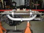
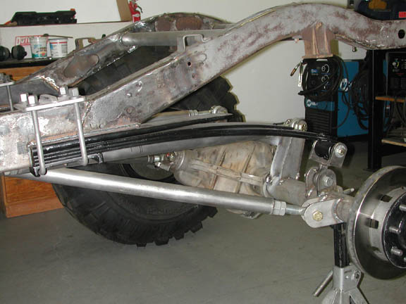
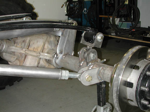
 The
springs use a shackle to attach to the axle housing. The shackle was made by
welding a section of channel iron to the end of a spherical rod end. The rod
end (Heim joint) is the same as is used on the four links, and the tabs welded
onto the axle housing are also the same. On a quarter elliptical suspension,
the ride height is adjusted by moving the mounting tabs forward or aft on the
circumference of the axle tube. If the tab is moved forward, the rod end moves
forward and down relative to the eye of the spring. This moves the top of the
axle closer to the spring eye and thus decreases the height of the rear end.
Right now I have the tabs placed nearly on top of the axle tube. The springs
are so flexy that I anticipate the weight of the cab and box will place the
ride height about right.
The
springs use a shackle to attach to the axle housing. The shackle was made by
welding a section of channel iron to the end of a spherical rod end. The rod
end (Heim joint) is the same as is used on the four links, and the tabs welded
onto the axle housing are also the same. On a quarter elliptical suspension,
the ride height is adjusted by moving the mounting tabs forward or aft on the
circumference of the axle tube. If the tab is moved forward, the rod end moves
forward and down relative to the eye of the spring. This moves the top of the
axle closer to the spring eye and thus decreases the height of the rear end.
Right now I have the tabs placed nearly on top of the axle tube. The springs
are so flexy that I anticipate the weight of the cab and box will place the
ride height about right.
Here are two more pictures of the rear suspension.
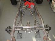
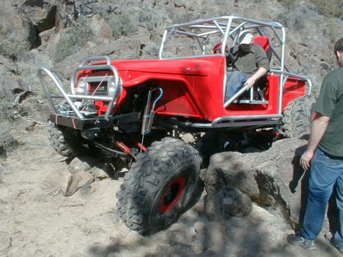
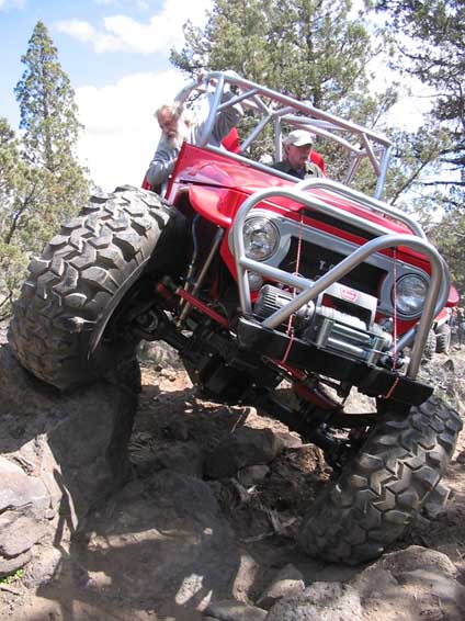
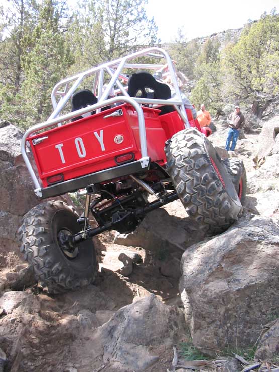
Below are some pictures that illustrate the suspension
in action. As you can see the Truggy articulates nicely. I still need to play
with different combinations of bump stops and limiting straps so that the drop
is controlled properly and the tires do not rub on the box or hit the front
fenders.
Suspension Upgrade
Although the suspension worked pretty good for
three years, my front suspension had some problems:
 1)
When the axle would drop (say at the top of a ledge without pulling the front
down with the winch) and the spring pack would open up, all of the unsprung
weight was placed on the primary leaf. Bent and broken primary leafs were a
common feature.
1)
When the axle would drop (say at the top of a ledge without pulling the front
down with the winch) and the spring pack would open up, all of the unsprung
weight was placed on the primary leaf. Bent and broken primary leafs were a
common feature.
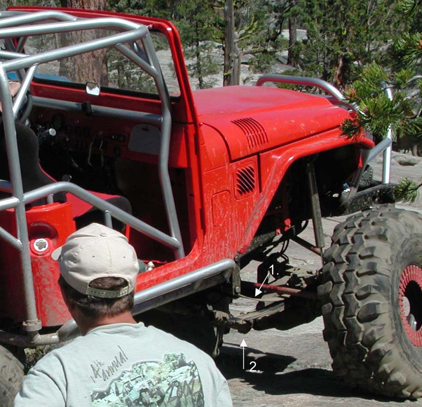
22) When the axle would drop the pinion rotates downward and
moves away from the transfer case. In my case, the pinion would rotate so much
that the 1410 series u-joint would bind and the driveshaft would pull apart
(even with a 12" slip joint). Also, as shown in the picture below, the
rotated pinion would often hit rocks . I ruined the driveshaft yoke by grinding
it on rocks when the pinion was rotated down.
I chose to address these issues by replacing the front leaf
springs with coil-over shocks working through a 4-link suspension system.
Front 4-Link Suspension

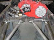
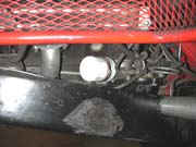
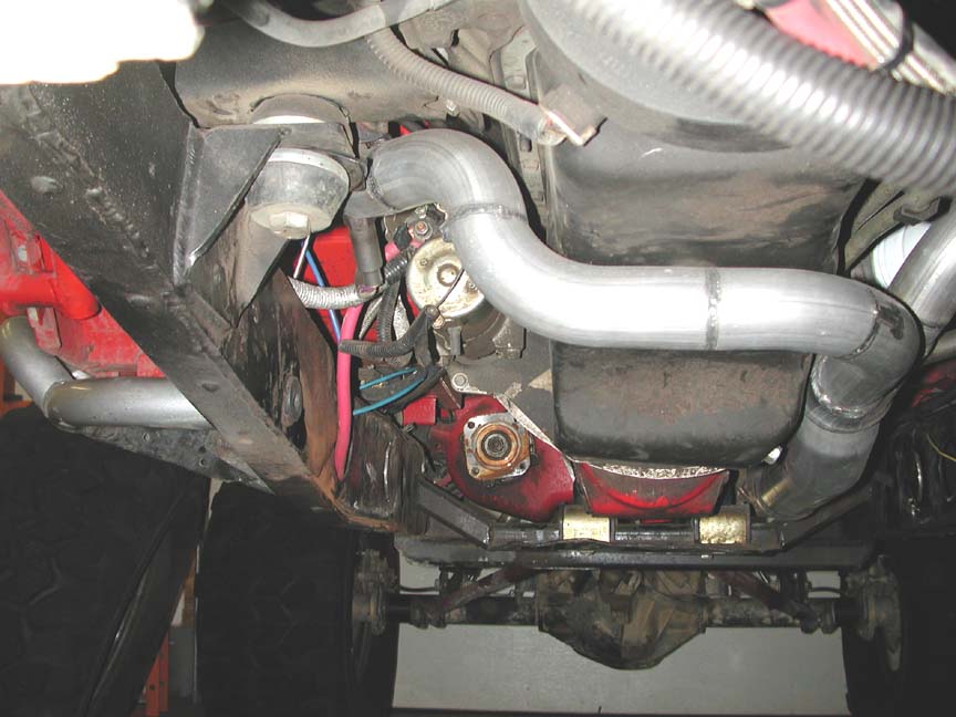
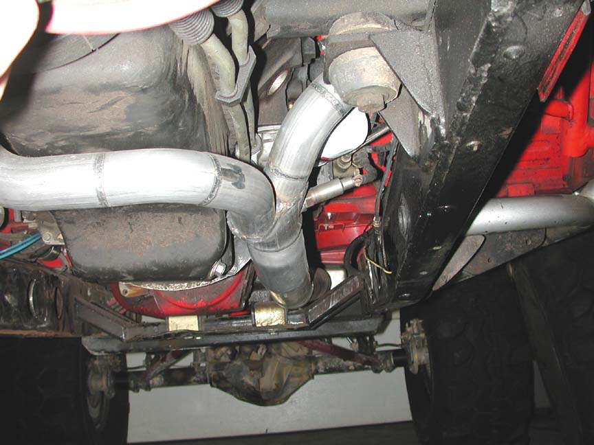
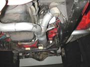 Front
four-link suspensions need to fit into a limited amount of space, and this poses
some problems. When I originally installed the engine, I used the common Walker
"crossover" exhaust pipe. In addition to being butt-ugly, this crossover
exhaust takes up an incredible amount of space. I made a new exhaust system
using a collection of 45, 60 and 90 degree mandrel-bent, 2" exhaust tube.
The goal was to tuck the exhaust as close as possible to the oil pan, keep it
as high as possible and free up space on either side of the inner frame rails.
This created considerably more room on the passenger's side of the engine bay(
pic on right).I was able to keep the exhaust high and tucked up next to the
pan.
Front
four-link suspensions need to fit into a limited amount of space, and this poses
some problems. When I originally installed the engine, I used the common Walker
"crossover" exhaust pipe. In addition to being butt-ugly, this crossover
exhaust takes up an incredible amount of space. I made a new exhaust system
using a collection of 45, 60 and 90 degree mandrel-bent, 2" exhaust tube.
The goal was to tuck the exhaust as close as possible to the oil pan, keep it
as high as possible and free up space on either side of the inner frame rails.
This created considerably more room on the passenger's side of the engine bay(
pic on right).I was able to keep the exhaust high and tucked up next to the
pan.
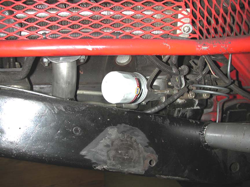
 A
lot of the space on the left rear side of the engine is occupied by the traditional
oil filter assembly.This assembly mounts the filter vertically and requires
the large-sized filter. Some late-model GM engines used a much smaller oil filter
assembly (GM part # 12562833). In this assembly the filter is mounted horizontally.
In addition, the assembly accepts the much smaller ( NAPA 21040) filter. As
you can see below, the entire oil filter is positioned above the frame rail,
completely out of the way of the link assembly.
A
lot of the space on the left rear side of the engine is occupied by the traditional
oil filter assembly.This assembly mounts the filter vertically and requires
the large-sized filter. Some late-model GM engines used a much smaller oil filter
assembly (GM part # 12562833). In this assembly the filter is mounted horizontally.
In addition, the assembly accepts the much smaller ( NAPA 21040) filter. As
you can see below, the entire oil filter is positioned above the frame rail,
completely out of the way of the link assembly.
The new exhaust and oil filter give considerably more room for
the links and mounts.
 In
the hope of providing some useful informationI thought I would share three tricks
that I found especially useful for this project. This project was made much
easier by making use of three "devices" designed to either move or
locate the axle or the four links. Since I did this project alone in my shop
and I only have two hands, reliance on devices like these really helped.
In
the hope of providing some useful informationI thought I would share three tricks
that I found especially useful for this project. This project was made much
easier by making use of three "devices" designed to either move or
locate the axle or the four links. Since I did this project alone in my shop
and I only have two hands, reliance on devices like these really helped.
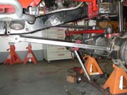
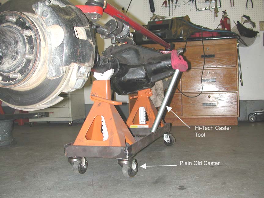
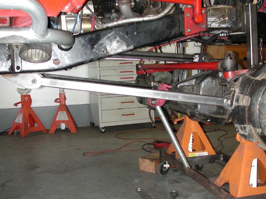
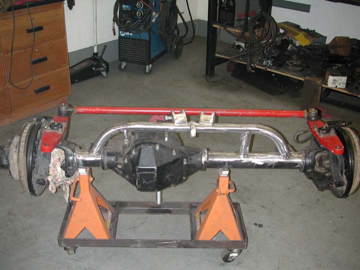
1. Over the entire course of this project I probably have moved
the front axle in and out from underneath the frame about 20 times The project
is much easier if you have the axle at the appropriate ride height on a moveable
dollie. Here is a simple dollie I made from 1.5" x .25" angle iron
and two small jack stands. It allows the axle to be easily moved by one person.
It also allowed me to determine the desired caster setting once and then keep
that fixed with a simple tube supporting the pinion.

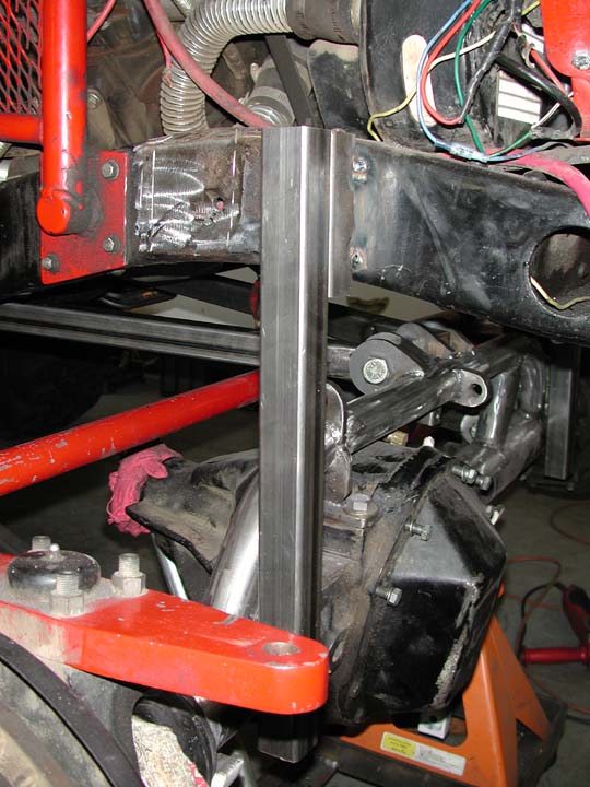
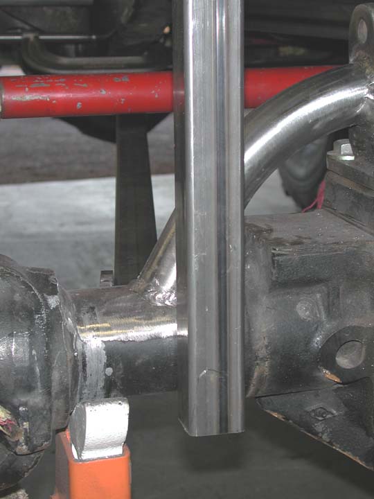
2. Because the axle was moved in and out so many times, it was
very helpful to be able to quickly and precisely re-locate the axle in the desired
final position. I did this by welding some 1.5" square tube onto the side
of the frame rails. I determined the desired positioning of the axle and tack-
welded these tubes to the frame before I cut off the leaf springs. To the extent
that the frame was straight before I cut off the leaf springs, the axle should
be located square. I moved the front axle forward by 4 inches -- giving me a
new wheelbase of 110". The tubes locate the axle both fore and aft and
laterally (by aligning the edge of the centersection against the tube). With
the axle on its dollie, I could quickly and easily position the axle right where
I wanted it to be -- and keep it there during the construction.
 3.
The link tabs were positioned and tack-welded into place using "construction
links" made from 1.5" square tube. By using the square-tube-links
I was able to A) keep the link tabs at the desired spacing of 1.5", B)
keep the link tabs parallel with each other, and C) keep the tabs on the two
ends of the link parallel. By keeping the tabs on the different ends of the
links parallel with each other, the heim joints have no misalignment in the
rest position.
3.
The link tabs were positioned and tack-welded into place using "construction
links" made from 1.5" square tube. By using the square-tube-links
I was able to A) keep the link tabs at the desired spacing of 1.5", B)
keep the link tabs parallel with each other, and C) keep the tabs on the two
ends of the link parallel. By keeping the tabs on the different ends of the
links parallel with each other, the heim joints have no misalignment in the
rest position.

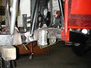
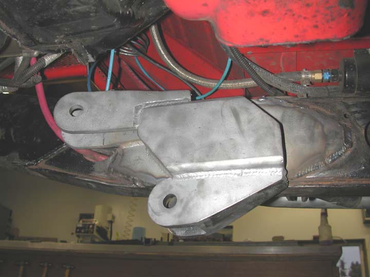
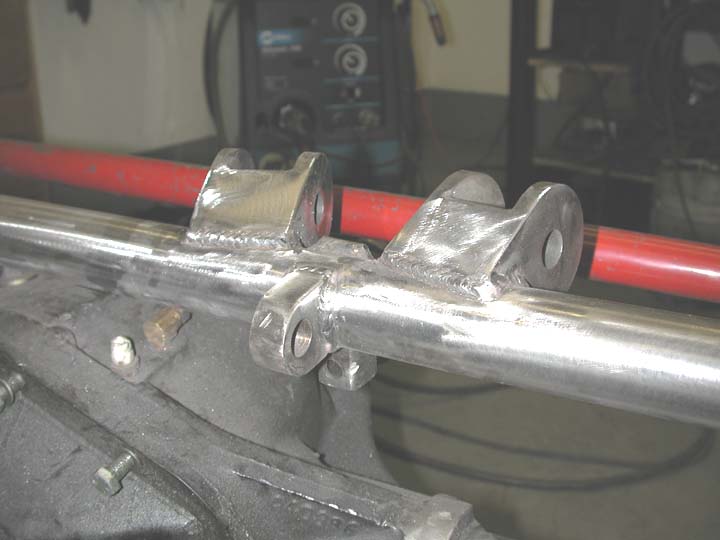
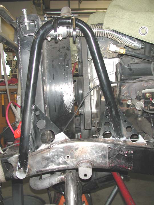
 Here
are the frame link mounts. These are one-piece units fabricated with a 13x5x1/4
scab plate, a 7x4x2x1/4 piece of rectangular tube with the open ends boxed,
and 4 pieces of 2 1/2 x 3/8 flat bar for the link tabs. The rectangular section
serves as a platform to weld the tabs onto.
Here
are the frame link mounts. These are one-piece units fabricated with a 13x5x1/4
scab plate, a 7x4x2x1/4 piece of rectangular tube with the open ends boxed,
and 4 pieces of 2 1/2 x 3/8 flat bar for the link tabs. The rectangular section
serves as a platform to weld the tabs onto.
Passenger side on the left and driver's side on the right. For
positioning reference above the hanger you can see the bellhousing (black) and
the front of the SM465 (red). The fit is still so tight on the driver's side
that I had to weld in the hanger with the upper Heim joint bolted in. If and
when that rod end fails, I will have to cut out the exhaust to replace it.
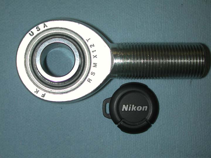
 The
links themselves are 1.5" o.d. DOM tube with a .375" wall. Before
you think I am crazy for using such small tube for the links, let me add that
the tubes are 4340 Cr-Mo alloy, and that they have been heat treated to a hardness
of RC 40. My calculations indicate that the yield strength of these links should
exceed that of a 2" DOM tube with a 0.5" wall.Eye-to-eye length for
the lower links is 34" and the upper links are 31" in length. I tried
to make them longer, but I simply did not have the room. Rod ends are F-K Heims
with a shank that is .875" in diameter and a bore of .750". These
Heims have a static load rating of 55,000 lbs.
The
links themselves are 1.5" o.d. DOM tube with a .375" wall. Before
you think I am crazy for using such small tube for the links, let me add that
the tubes are 4340 Cr-Mo alloy, and that they have been heat treated to a hardness
of RC 40. My calculations indicate that the yield strength of these links should
exceed that of a 2" DOM tube with a 0.5" wall.Eye-to-eye length for
the lower links is 34" and the upper links are 31" in length. I tried
to make them longer, but I simply did not have the room. Rod ends are F-K Heims
with a shank that is .875" in diameter and a bore of .750". These
Heims have a static load rating of 55,000 lbs.
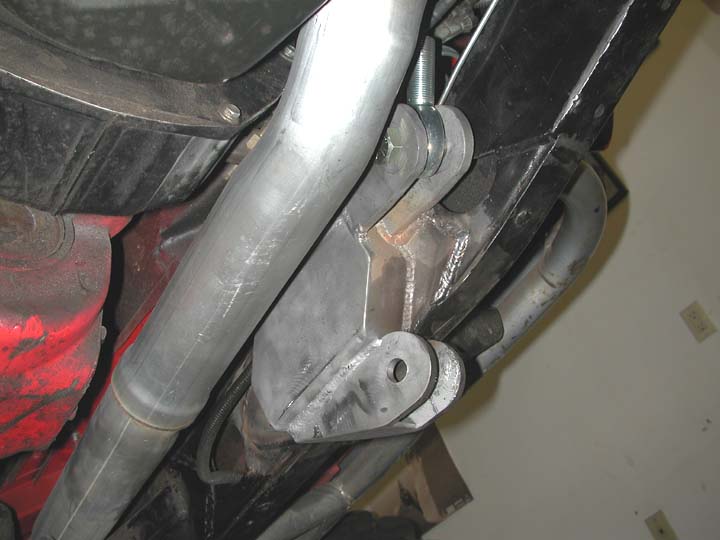
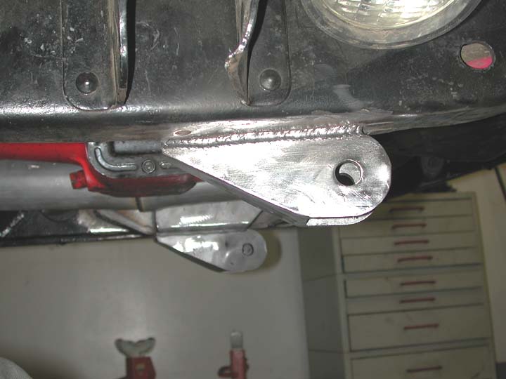
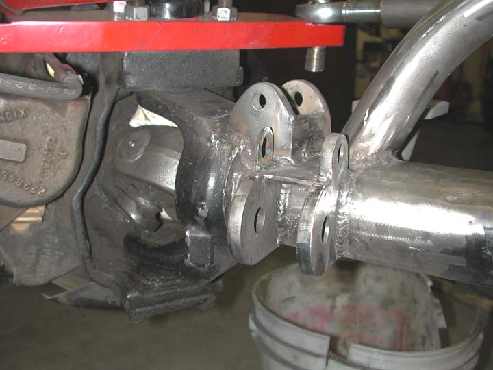
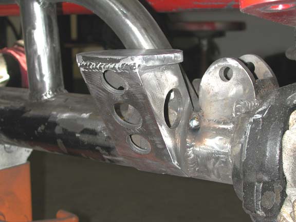
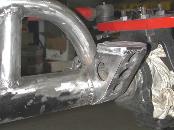
 Here
is a view of the lower frame link tab. I originally tried to come up with a
4-link design that would locate all of the link hangers above the bottom of
the frame. Such a design would have the lower link hanger positioned on the
outer side of the frame (like the Proffitt Cruisers). After much thought, measuring
and consternation, I concluded that the outside-of-the-frame geometry for the
lower links will only work with full-width axles. With a front axle that is
narrowed, any large tire will hit the link when the steering is at full. Soooo,
I compromised again and placed the link mount inboard and beneath the frame.
I tried to keep it as high as possible and reasonably sturdy.
Here
is a view of the lower frame link tab. I originally tried to come up with a
4-link design that would locate all of the link hangers above the bottom of
the frame. Such a design would have the lower link hanger positioned on the
outer side of the frame (like the Proffitt Cruisers). After much thought, measuring
and consternation, I concluded that the outside-of-the-frame geometry for the
lower links will only work with full-width axles. With a front axle that is
narrowed, any large tire will hit the link when the steering is at full. Soooo,
I compromised again and placed the link mount inboard and beneath the frame.
I tried to keep it as high as possible and reasonably sturdy.
Axle Truss
 I
chose to use the simple and successful tube-style axle truss.The truss consists
of 1.75" DOM with a .188" wall thickness. Neither of my two friends
with tube benders (one a JD2 and the other a Pro Tools) who usually bend for
me were able to bend the .188 wall tube, so I had it done by the local company
that makes the Tubeshark (http://www.tubeshark.com/) If anyone is really serious
about bending tube, and has a lot of $$ to invest, this is one sweet bender.
I
chose to use the simple and successful tube-style axle truss.The truss consists
of 1.75" DOM with a .188" wall thickness. Neither of my two friends
with tube benders (one a JD2 and the other a Pro Tools) who usually bend for
me were able to bend the .188 wall tube, so I had it done by the local company
that makes the Tubeshark (http://www.tubeshark.com/) If anyone is really serious
about bending tube, and has a lot of $$ to invest, this is one sweet bender.
The truss is supported by a vertical tube on the driver's side
and a short tab that ties into the original D60 spring mount. I have zero confidence
in my ability to effectively weld on the Dana center section, and hence avoided
that experience.
The upper axle link tabs are again made of 2.5" x .375"
flat bar. After notching the tabs for placement at the proper angle, I weld
each tab on each side to the tube truss and than add the "cap" for
additional support. The front of the truss also has a .75" thick tab for
the winch mount and the rear of the truss has a tab for the brake line junction.
More pics of the axle are given below.
 Here
are two views of the bump-stop platforms.
Here
are two views of the bump-stop platforms.
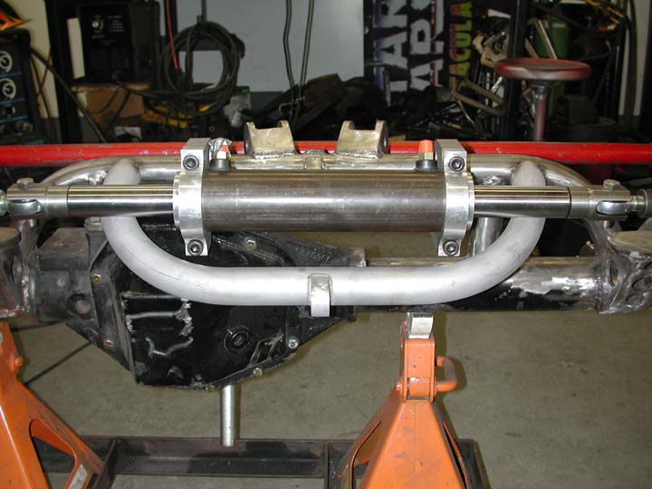
 Here is the nearly completed front axle. The hydraulic ram is
a PSC unit -- 2.5" piston diameter, 8" stroke and .250 wall cyllinder.
Aligning a double-ended ram is a PITA with only two hands.
Here is the nearly completed front axle. The hydraulic ram is
a PSC unit -- 2.5" piston diameter, 8" stroke and .250 wall cyllinder.
Aligning a double-ended ram is a PITA with only two hands.
 I
got lazy and had the mounting brackets for the ram made from 1" thick mild
steel -- cut with a CNC water jet. It was very cool to watch that machine work.
I
got lazy and had the mounting brackets for the ram made from 1" thick mild
steel -- cut with a CNC water jet. It was very cool to watch that machine work.
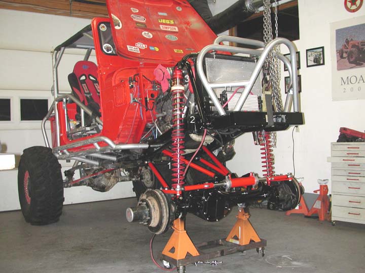
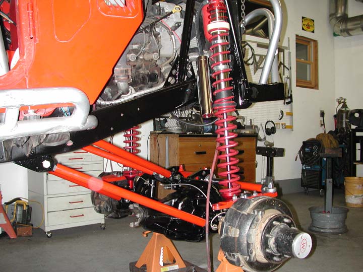
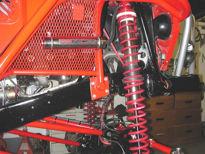
 I
also needed to fabricate new hoops for the coilover shocks as well as bump stop
cans and tabs for the limiting straps. Note the large
gussets on the frame. I also made a tube connecting the two shock hoops above
the engine.
I
also needed to fabricate new hoops for the coilover shocks as well as bump stop
cans and tabs for the limiting straps. Note the large
gussets on the frame. I also made a tube connecting the two shock hoops above
the engine.
Coilovers are 16 inch travel, 2.5" diameter Sway-A-Way
units. Springs are Eibach and include 1) a 16" primary with a spring rate
of 350 lbs/in. 2) a secondary coil with a spring rate of 150 lbs/in. and 3)
a 6" long tender spring that provides just enough push to keep the primary
spring seated in the bottom cup on full extension.

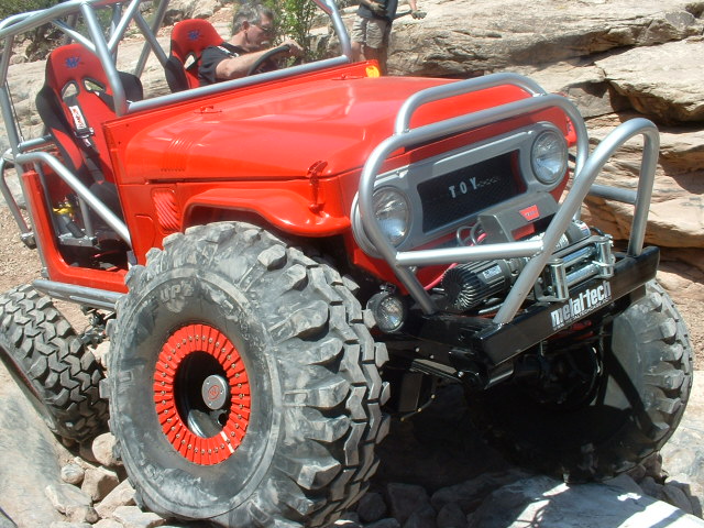
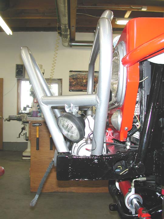
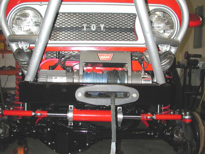
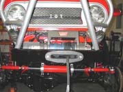 By
ditching the leaf springs I was able to remove 7" from the front frame
rails but still keep a small bumper and my stinger and bib hoop. My approach
angle is going to be greatly approved -- no more of the bulldozing for me. I
also chose to set the winch down between the frame rails and put the fairlead
in the middle of the bumper instead of on top.
By
ditching the leaf springs I was able to remove 7" from the front frame
rails but still keep a small bumper and my stinger and bib hoop. My approach
angle is going to be greatly approved -- no more of the bulldozing for me. I
also chose to set the winch down between the frame rails and put the fairlead
in the middle of the bumper instead of on top.
 The
front suspension consists of a more-or-less traditional spring-over axle suspension
combined with a shackle reversal. There are, however, several minor twists that
will provide increased flex and articulation. The first of these twists are
the springs themselves. They are the rear springs from an FJ60 wagon. The spring
packs contain 7 leaves and the individual leaves are tapered and include anti-friction
pads at each end. They were nearly flat when removed from the heavy wagon. The
advantage they have over stock FJ45 (or 40) springs is in their length -- 45.7"
compared to the stock FJ40/45 length of 42". For comparison, FJ55 springs
are 45.5 " in length.(For consistency, the lengths quoted here are taken
from Rob Mullen's Land Cruiser FAQ [http://www.off-road.com/tlc/faq/frame.html#HD_NM_3])
The longer spring, when used in conjuction with a long shackle allows for more
drop and hence better articulation. Another advantage is that the 60-series
springs used the larger spring eyes and bushings than those on the 40/45. Use
of the large spring eye with rubber bushings allows for more twist in the spring
relative to the spring pin, and hence more articulation. The rubber bushings
will wear out quicker than poly bushings, but who cares on a trail rig like
this .
The
front suspension consists of a more-or-less traditional spring-over axle suspension
combined with a shackle reversal. There are, however, several minor twists that
will provide increased flex and articulation. The first of these twists are
the springs themselves. They are the rear springs from an FJ60 wagon. The spring
packs contain 7 leaves and the individual leaves are tapered and include anti-friction
pads at each end. They were nearly flat when removed from the heavy wagon. The
advantage they have over stock FJ45 (or 40) springs is in their length -- 45.7"
compared to the stock FJ40/45 length of 42". For comparison, FJ55 springs
are 45.5 " in length.(For consistency, the lengths quoted here are taken
from Rob Mullen's Land Cruiser FAQ [http://www.off-road.com/tlc/faq/frame.html#HD_NM_3])
The longer spring, when used in conjuction with a long shackle allows for more
drop and hence better articulation. Another advantage is that the 60-series
springs used the larger spring eyes and bushings than those on the 40/45. Use
of the large spring eye with rubber bushings allows for more twist in the spring
relative to the spring pin, and hence more articulation. The rubber bushings
will wear out quicker than poly bushings, but who cares on a trail rig like
this .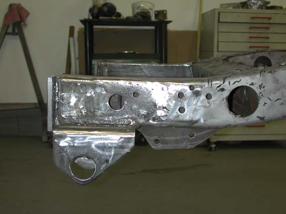

