Front Axle
We chose to lift our FJ40 by placing the stock, nearly flat springs on top of the axle housings. Our goals for this conversion were to obtain 1) better ground clearance, 2) room for larger tires (35's or 36's, not the tiny 29's shown in these photos), and 3) better articulation. Another advantage of a spring over conversion is that the weight of the frame and body becomes supported by the axle housings with the springs resting naturally on top of the axle tubes. In the stock configuration, the eight U-bolts had to carry all of the weight of the vehicle and be subject to the forces associated with acceleration, deceleration and axle movement. In the SOA the role of the U-bolts is reduced to primarily holding the axle housings in place and dealing with twisting associated with articulation, acceleration, etc.
We caution that a decision to do an SOA conversion should only be made with careful attention to the intended use of the vehicle, driving habits and trade-offs resulting from significantly increasing the vehicle's center of gravity. Unless sepecial modifications are made, the SOA produces a lift of at least 5-6". In our particular case, the final lift was 6.3" measured at the spring centering bolt. This amount of lift requires modifications in a number of components including drive shafts, brake lines and shock absorbers, all adding considerable cost to the project as well.
Although the SOA conversion is conceptually straightworward,
careful attention must be made in order to ensure proper steering geometry
(esp. caster angle) for the front axle and driveline angles on both.
Given the relatively short driveshafts on an FJ40, the lift associated
with an SOA results in an unacceptable angle on the pinion U-joint if the
pinion shaft remains in its stock, nearly horizonal position. The
solution is to rotate the axle housing so that the pinion shaft ideally
points directly toward the transfer case yoke, thereby entirely eliminating
the angle on the pinion U-joint (see comments on driveshafts below).
However, rotation of the front axle housing alters the steering geometry,
specifically the caster angle, to an unacceptable degree. In order
to maintian proper steering geometry, the front axle tube must be cut just
inside the knuckle at each end and the knuckles rotated an equal but opposite
number of degrees as the "pumpkin" is rotated up. Additional information
on this subject can be found in Rod LaHaise's edited version of Greg
Cooper's 1993 Toyota Trails article on SOA conversions. We also
recommend reading the approach used by Danny Warden, as described in the
9-97 issue of 4WD & Sport Utility Magazine.
 A
primary component of our SOA is a used front axle housing modified by Greg
Cooper and his staff at Fabtech Mfg. of Kelwona, B.C. (unfortunately now
out of business). After breaking one axle housing trying to do this
"cut and turn" modification on our own, we decided to invest the funds
to purchase a housing professionally modified on a gig that ensures precise
rotation of both knuckles relative to the pumpkin. The Fabtech housing
included new spring saddles, steering stops, extended shock mounts, an
new breather port at the top of the housing, and a truss to strengthen
the long leg of the axle tube. The gear lube filling/examination
fitting on the front of the pumpkin was also raised approximately 1.5"
in order to ensure proper lubrication to the pinion bearing.
A
primary component of our SOA is a used front axle housing modified by Greg
Cooper and his staff at Fabtech Mfg. of Kelwona, B.C. (unfortunately now
out of business). After breaking one axle housing trying to do this
"cut and turn" modification on our own, we decided to invest the funds
to purchase a housing professionally modified on a gig that ensures precise
rotation of both knuckles relative to the pumpkin. The Fabtech housing
included new spring saddles, steering stops, extended shock mounts, an
new breather port at the top of the housing, and a truss to strengthen
the long leg of the axle tube. The gear lube filling/examination
fitting on the front of the pumpkin was also raised approximately 1.5"
in order to ensure proper lubrication to the pinion bearing.
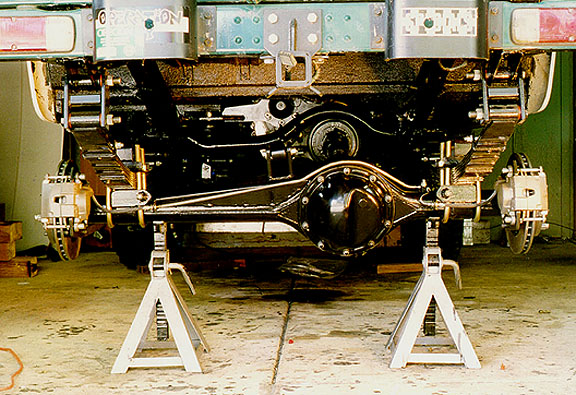
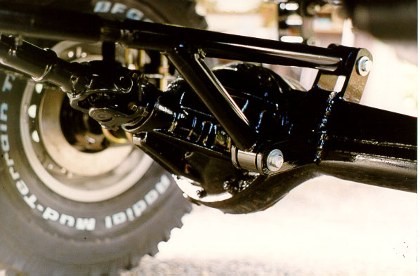
The Fabtech housing is shown in the above photo mounted
to our modified springs. Note the rotation of the third member up
toward the transfer case. With our specific spring and shackle
arrangement, the angle of the pinion shaft is 15 degrees above
horizontal. Incorporation of the new front axle housing required
a complete rebuild of the knuckles, including new seals, knuckle shims,
bearings & races and gaskets. Careful examination of this photo also
shows the extended mounts for the shock absorber and several useful shop
tools for this conversion including the TLC Body and Chassis Repair Manual.
The VORTEC engine, NV4500 and Transfer case are hiding beneath the yellow
covering in the background.
 As
shown in the photo to the left, we used the stock u-bolt plates modified
to include a bump-stop. This piece of 1.5" x .25" steel plate was
bent into a broad "U", cut to fit 2" above the top leaf of the spring pack
and then welded to the u-bolt plate. Three of the four u-bolts are stock
replacements (always use new u-bolts when replacing or changing springs).
The inner u-bolt on the passenger's side (where the spring saddle overlaps
on the side of the pumpkin) required a larger u-bolt because of the degree
of rotation of the housing. I believe that Danny Warden only rotates
the housing the amount allowed by the stock u-bolts. The Fabtech approach
involves a greater rotation and replacement of the limiting u-bolt.
We also chose to utilize the extra flat surface area of the truss to weld
a hefty bracket for the Rancho steering stabilizer directly to the housing.
As
shown in the photo to the left, we used the stock u-bolt plates modified
to include a bump-stop. This piece of 1.5" x .25" steel plate was
bent into a broad "U", cut to fit 2" above the top leaf of the spring pack
and then welded to the u-bolt plate. Three of the four u-bolts are stock
replacements (always use new u-bolts when replacing or changing springs).
The inner u-bolt on the passenger's side (where the spring saddle overlaps
on the side of the pumpkin) required a larger u-bolt because of the degree
of rotation of the housing. I believe that Danny Warden only rotates
the housing the amount allowed by the stock u-bolts. The Fabtech approach
involves a greater rotation and replacement of the limiting u-bolt.
We also chose to utilize the extra flat surface area of the truss to weld
a hefty bracket for the Rancho steering stabilizer directly to the housing.
 Another
consequence of the SOR (lowering the front axle 5-6" is that the stock
steering arm on the passenger's side ends up at the same level as the spring
pack, thus preventing connection with the drag link and tie rod.
The solution here is to use a double steering arm. We chose the arm
sold by Aqualu Industries of Kelwona,
B.C. This arm is foundary cast from 4140 (?) alloy steel and precision
machined to fit the Cruiser steering knuckles using the stock studs, cone
washers and tie rod ends. The arm is very similar to the one sold
by Fabtech, but slightly smaller, thus reducing the possibility of rubbing
on the wheel or tire under extreme conditions. With this configuration
(click on the arm image for a view of the installed component), the drag
link from the Saginaw steering box goes above the spring, and the tie rod
is below the spring. The drag link and tie rod are parallel and essentially
horizontal.
Another
consequence of the SOR (lowering the front axle 5-6" is that the stock
steering arm on the passenger's side ends up at the same level as the spring
pack, thus preventing connection with the drag link and tie rod.
The solution here is to use a double steering arm. We chose the arm
sold by Aqualu Industries of Kelwona,
B.C. This arm is foundary cast from 4140 (?) alloy steel and precision
machined to fit the Cruiser steering knuckles using the stock studs, cone
washers and tie rod ends. The arm is very similar to the one sold
by Fabtech, but slightly smaller, thus reducing the possibility of rubbing
on the wheel or tire under extreme conditions. With this configuration
(click on the arm image for a view of the installed component), the drag
link from the Saginaw steering box goes above the spring, and the tie rod
is below the spring. The drag link and tie rod are parallel and essentially
horizontal.
In some SOA conversions, the spring pack has been flipped
front to rear. Although this operation keeps the military wrap at
the fixed pivot point (where it belongs), it also moves the axle housing
forward (beacuse the centering pin for the leaf pack is not in the center).
As noted above, we maintained the stock position of the axle by adding
1.5" to the front frame rails. We did flip the #2 leaf (with the military
wrap) in order to place it at the pivot point, now locaed at the front
of the frame. We did this by removing this leaf from the pack and
redrilling the centering hole. We believe this approach is superior
to flipping the entire spring packs.
Rear Axle
Compared to the front axle, required modifications to
the rear housing were relative minor, owing to the fact that it is not
necessary to account for factors crucial for steering geometry (e.g., caster).
Nevertheless significant modifications were made to the rear housing in
order to add strength, flexibility and safety. We welded a 3/16"
thick truss on the top of the long side of the housing for additional strength
(similar to that on the front). The stock spring saddles were removed
and new ones were fabricated from 1/4" wall channel stock to rest on top
of the axle housing. Prior to final welding, the spring saddles
were placed on the housing, full weight was applied to the housing, and
the pinion shaft was then rotated to provide the desired geometry for the
rear drive shaft. To the rear of the saddles are welded 3/8" thick plates
to serve as mounts for the shock absorbers. This arrangement places
the bottom of the shocks out of harms way and allows of use of stock-length
shock absorbers. Heavy duty rear spring shackles were also fabricated.
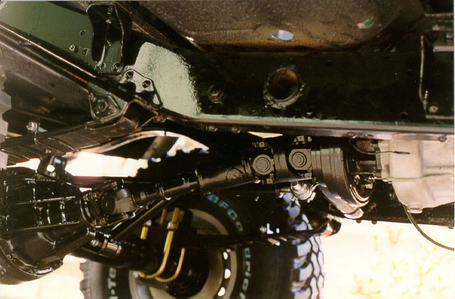
The SO resulted in an angle of the rear driveshaft that
is excessive for a traditional u-joint assembly. We therefore fabricated
a custom driveshaft consisting of the stock flange and u-joint, a shortened
main shaft with stock slip joint and a new constant velocity (double cardan-type)
joint on the transfer-case end. We selected a Saginaw CV joint over
the Spicer equivalent because of greater strength and slightly more angular
tolerance. The Saginaw CV is mated to the stock parking brake drum
with a custom flange adapter machined to fit the TLC bolt pattern on the
transfer-case side and the Saginaw bolt pattern on the driveshaft side.
I
Additional modifications to the rear axle included installation
of disc brakes and new brake lines.
Cruise
Home For Additional Conversions and Features
|
Want info on how to JOIN this ring?? |
| [Prev] [Skip Next] [Random] [List Sites] [Next] |