

 In
1996 GM introduced their new state-of-the-art line of Vortec Engines.
These engines were designed to meet the combined needs of performance,
fuel economy and limited emissions, and represent the evolution in engineering
from traditional carburated engines through the more advanced TBI and TPI
fuel injected engines developed some 10 years earlier. Between 1996
and 1998, GM produced three basic Vortec engines: the 4.3L (V-6, 264 c.i.),
the 5.7L (350 c.i.) and the 7.4L ("big block" 454 c.i.). In the simplest
of terms, the Vortec is a Sequential Port Fuel Injection (SFI) engine,
which utilizes a sophisticated computer system known as the "Vehicle Control
Module", or VCM for short, in conjunction with numerous sensors to monitor
and adjust the control of the engine. Although the electronics are
sophisticated and complicated for an old Cruiserhead like me, they result
in an impressive engine that is capable of performing for up to 100,000
miles without a tune-up.
GM V-8 engines have been popular conversions for Land Cruisers for many years. A significant advantage of the Vortec engine over its predecessors is that if installed with all features, it should fully meet all federal and state emission standards. Brian Schreiber at BTB Products of San Jose, CA has installed new, crate, Vortec engines in numerous Land Cruisers during the past two years and has had no problems meeting the strict CARB standards. BTB perfected the Vortec-TLC conversion, does quality work, and their Vortec Cruisers are truly impressive (but also very expensive).
With the imminent death of the 2F in my '78 FJ40, I was fortunate to find, and quick enough to buy, a like-new 5.7L Vortec from a salvage yard. The engine came out of a '96 3/4-ton Chevy Silverado with less than 8,000 miles on the odometer. The truck was involved in a rollover that totalled the rig without damage to the engine. After a complete inspection, including running of the moror, I obtained the engine in September of '97, and after rebuilding the suspension on the FJ40, mating the engine to a '95 NV4500 transmission and figuring out how to mate the Vortec electronics to the Cruiser, had it running in May of '98. All work was done by me in my small Cruiser-dedicated home shop.
The 5.7L Vortec is based on the traditional 350 c.i. engine
originally introduced by GM, I believe in 1968. It has a 4-bolt main,
cast iron block and heads, and as a short-block is not significantly different
from its predecessors (differences are primarily in the design of the heads,
the camshaft and the addition of block ports for the various sensors).
The sequential port fuel injection system (SFI) has each injector controlled
by the VCM which regulates the air : fuel mixture based on continuous readings
from sensors such as the mass air flow (MAF), manifold pressure (MAP) engine
coolant temperature (ECT), rpm, throttle position sensor (TPS), vehicle
speed (VSS) and four exhaust sensors (see exhaust system below).
The engine utilizes data from nearly 20 sensors providing information for
real-time control of the engine by the VCM. In addition
to controlling the air : fuel mixture the VCM also controls and constantly
adjusts an HEI ignition system, as well as camshaft retard. The stock 5.7L
develops 255 HP (compared to 120 from the 2F) and 330 ft. lbs. of torque
@ 2800 rpm (compared to 240 ft.lbs. @ 2200 rpm for the 2F). AND
the Vortec weighs 200 lbs. less than the 2F! Compared to the
2F, the Vortec is is a clean burning, fuel efficient, EFI muscle engine.
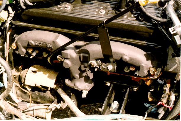
The engine is mounted to the TLC frame using the standard V-8 motor mounts supplied by Advanced Adapters Inc. The top of the passenger's-side motor mount is shown in this photo (just below the front of the exhaust manifold). A scab plate was first welded on the inside of each frame rail. The engine, with NV4500 and transfer case attached, was lowered into the frame and the motor mounts were clamped into their approximate position and then adjusted by multiple measurements. A great deal of time was spent positioning, measuring and repositioning the motor mounts. Owing to the length of the NV4500, I wanted to place the engine as far forward as prudent. Furthermore, with the spring-over conversion, I wanted to place the drive train relatively low in the frame and tilted somewhat down in the rear in order to minimize 1) the center of gravity and 2) the angle of the rear driveshaft. The final position has the front of the AA motor mounts located 9.5" aft of the rear of the shock towers. The centerline of the crankshaft is positioned 0.25" toward to the driver's side of the frame centerline.
The above photo also illustrates the one compromise of
Vortec parts I needed to make for this conversion -- namely the exhaust
manifolds. The Vortec exhaust manifolds represent a significant advance
over previous GM versions, and I really liked them. They are large,
relatively free flowing and nicely hug the block, below the spark
plugs. Unfortunately, however, the driver's side manifold interferes
with the location of the clutch slave cylinder on the AA bellhousing.
The best solution for this problem (at the time) was to replace the Vortec
exhaust manifolds with realtively free-flowing, GM manifolds from pre-emissions
days. I chose to follow the BTB approach and install a set of rams-horn
manifolds from a '76 Corvette (shown in the photo above). In order
to supply the EGR system with hot exhaust, I fabricated a 1"-thick, stainless
steel flange with EGR port sandwiched between the driver's manifold exit
and the exhaust pipe. I believe a Vortec mated to an automatic transmission
may be able to retain the Vortec exhaust manifolds. If I were to
do this again with a manual transmission, I would explore the possibility
of using the new GM bellhousing with the internal clutch slave cylinder,
instead of the AA bellhousing and external clutch mechanism.
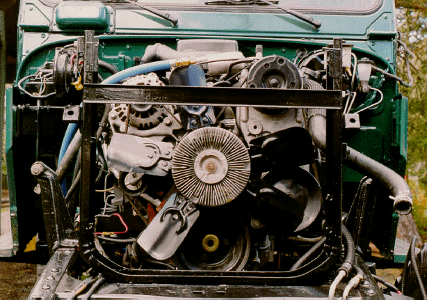
Cooling of the engine is accomplished with a 4-row, high
density radiator. In order to center the stock 19" Vortec fan on
the radiator and within a custom 5" deep fan shroud, the radiator frame
was moved 1.5" toward the passenger's side of the frame. I also elected
to install a crankcase-oil cooler (utilizing the stock Vortec autotranny
cooler) mounted in front of the radiator on the driver's side, and this
necessitated moving the radiator frame rearward 0.5" in order to provide
space for the oil cooler between the radiator and the TLC front bib.
The Vortec also came with a power-steering-fluid cooler that is mounted
on the inside of the driver's side front fender (below the VCM).
The Vortec does not use a standard thermostat; the VCM opens the
cooling system based on readings from the Engine Coolant Temperature (ECT)
Sensor. Based on my Autometer gauge, the coolant system opens at
190 degrees F. Driving, on and off-road, at an ambient temperature
of 105 degrees F (yes, it can get warm in Orygun), results in engine temperatures
in the range of 205-210 degrees F.
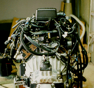 When
I brought the engine home, my wife immediately named it Medusa,
for the serpent-like wiring harness completely covering the top of the
beauty (ok, maybe her words were more like beast, but I considered it a
real beauty). Understanding the Vortec electronics and ultimately
mating the Vortec wiring harness with the existing TLC wiring was, for
this electronics-challenged Cruiserhead, the most difficult aspect of the
conversion. Fortunately, the salvage yard left the harness intact
and included nearly all of the components necessary for the conversion.
An absolute must for this conversion is acquisition of the GM Service Manuals
for the specific donor vehicle. For the '96 Chevy C/K trucks, there
are two volumes, each about 2" thick. Book 1 deals with the mechanical
aspects of the engine and Book 2 deals specifically with the electronics,
computer system and electrical diagnosis. It took me about 2 weeks
to figure out the electronics (for example, 92 separate wires are connected
to the VCM), but after understanding the logic and figuring out the wiring
diagrams, the required wiring was relatively straightforward. This task
was made easier by "wall-papering" one 12' x 10' wall of my shop with wiring
diagrams from the Service Manual. Many of the harness branches were not
needed (e.g., controls for auto-transmission , anti-lock brakes, cruise
control and SIR) and wires for these circuits were cut at appropriate locations
and then sealed/insulated with a combination of RTV and heat-shrink tubing.
New wiring was required for the fuel pump, vehicle speed sensor (VSS),
air-compressor switch and hi-P shutoff, a custom anti-theft device, and
all Autometer gauges.
| The fuel pump circuit is an illustative example of both the complexity and ingenuity of the Vortec electronics. I purchased a high-pressure (100 psi), in-line electric fuel pump and two fuel filters (both a high-P and a low-P filter) and mounted the pump on the passenger's-side frame across from the TC. When the ignition switch is turned to ON, the VCM activates a relay that runs the fuel pump for 2 seconds, and then turns it off. This is a sufficient time to build up enough fuel pressure for starting the engine. After those 2 seconds, power to the fuel pump is controlled by a switch in the oil pressure sending unit that closes when oil pressure is at or above 15 psi. So once the engine is started, the fuel pump runs continuously as long as oil pressure is greater than 15 psi. This feature has the obvious advantages of 1) saving the engine by turning off fuel flow in case of a loss of oil pressure, and 2) shutting off the fuel flow in case of an accident that stops the engine, or even a rollover (as the oil pump, sucks air up-side-down). Also, in order to prevent vapor-lock, the VCM activates the fuel pump relay and runs the pump for 2 seconds after the ignition switch is turned off. |
I had to lengthen the branch of the harness (36 wires) leading to a firewall connector located just inside the driver's side vent at the level of the top of the clutch pedestal. Once this was accomplished, it was a relatively simple task to make conncetors and plug in wires from the TLC ignition switch and provide appropriate power to the TLC fuse box, and thereby to all components of the FJ40 electrical system. Once appropriately switched and fused, power was supplied to all the necessary TLC circuits. Superfluous TLC wires (e.g., engine controls, ingition, etc.) were cut and sealed as described above.
The photo below shows the final installation of the Vortec in the TLC engine bay. We didn't realize how tight a fit it would be until we attempted to reinstall the fenders. While there is more that adequate room for the engine, arranging the mounting brackets for accessories such as the battery, air cleaner, VCM and fuse/relay center provided some challenges. As you can see, however, the final product is a clean fit.
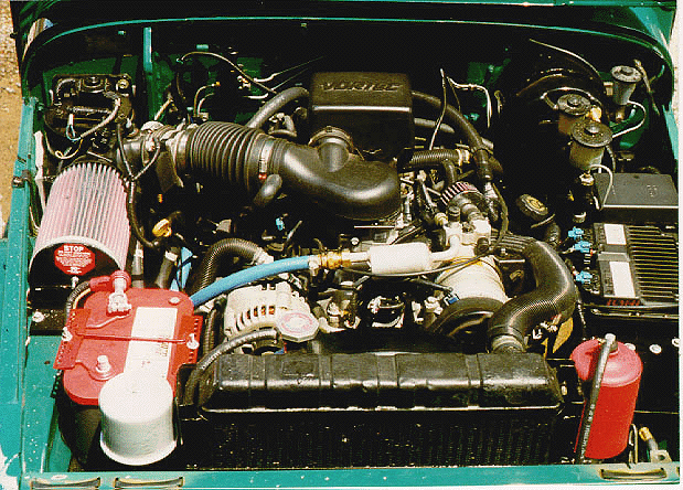
Accessories visible on the left (from front to rear) include
1) a K&N breather filter providing clean and dry air to both axle housings,
the NV4500 and the transfer case; 2) an Optima battery utilizing both side
and top posts; and 3) the new K&N Filtercharger air cleaner element
designed specifically for the Vortec. At the front of the block you
can see the top of the custom fan shroud, and the air compressor plumbing
(blue hose) leading from the Vortec A/C compressor to the air block (hidden
by the air intake, but see separate page for on-board air). Accessories
on the right-side of the photo include a Summit Racing radiator-overflow
canister (red), the VCM (black with cooling fins) and the fuse/relay center
(just in front of the brake master).
Exhaust System
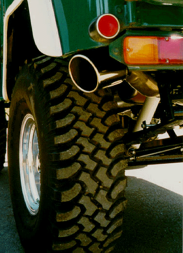
The exhaust system is the only part of this conversion project I was reluctant do by myself. We wanted a stainless steel system that would fit completely into the restricted space along the driver's side and above the bottom of the frame (a challenge for the most skilled of exhaust specialists). In order to achieve maximum performance from the Vortec, while simultaneously utilizing its potential for efficient emission control, we chose to employ a space-conserving version of the stock exhaust system shown below.
The exhaust system includes the following components:
Other items of interest in the under-cruiser photo (2nd
above) are the fuel lines (red) on the passenger's side frame rail, and
the speedometer/VSS assembly. The latter consists of a ratio converter
mating to the transfer case at the stock speedometer port. This is
a custom mechanical converter that corrects for the TC speedometer gear,
the tire size and the R/P ratio of the differential. The purpose of this
converter is to provide the spedometer industry standard of a 1:1 drive
ratio (1,000 rpm of the speedometer cable at 60 mph). Outboard of the ratio
converter is the Vehicle Speed Sensor (VSS). This is a Hall-effect
generator producing electrical pulses proportional to the vehicle speed.
The VSS signal is carried by the gray wire to an electronic amplifier/converter
mounted in the cab beneath the center console. This device processes
the signal and converts it to the form required by the Vortec VCM.
A traditional speedometer cable mates to the VSS and runs forward to the
Autometer gauge.
Cruise
Home For Additional Conversions and Features
|
Want info on how to JOIN this ring?? |
| [Prev] [Skip Next] [Random] [List Sites] [Next] |